| Electronic Transformers and Circuits is a free introductory textbook on transformers and related circuits. See the editorial for more information.... |

|

Home  Amplifier Circuits Amplifier Circuits  Inverse Feedback Inverse Feedback |
||||||||||||||||||||||||||


|
||||||||||||||||||||||||||
Inverse Feedback
If part of the output of an amplifier is fed back to the input in such a way as to oppose it, the ripple, distortion, and frequency response deviations in output are reduced. The amplifier gain is reduced also, but with the availability of high-gain tubes an extra stage or two compensates for the reduction in gain caused by inverse feedback, and the improvement in performance usually justifies it.
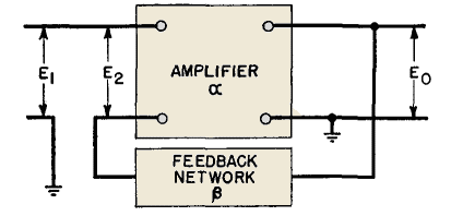
In the amplifier of Fig. 130, a network is shown connected to output voltage Eo; part of this output is fed back so that the input to the amplifier is
Here β is the portion of E0 which is fed back. If α is the voltage amplification of the amplifier and Er and EH are the ripple and harmonic distortion in the output without feedback, and α', E'R, and E'H are the same properties with feedback, the following equations hold, if α, ER, and EH are assumed to be independent: Without feedback,
With feedback,
these equations it can be shown that
With high-gain amplifiers and large amounts of feedback, the output ripple and harmonic distortion can be made astonishingly small. Likewise the frequency response can be made flat, even with mediocre transformers. Inverse feedback is not used in class C amplifiers, because the output and input are not linearly related.
Low phase-shift amplifiers benefit most from inverse feedback. Feedback in such amplifiers reduces size or improves performance, including phase shift. Transformer phase shift, therefore, is a vital property in feedback amplifiers and may take precedence over frequency response in some instances.
Phase shift at low and high frequencies is shown in Figs. 131 and 132 for transformer-coupled stages. At high frequencies, 180° phase shift is possible whereas at low frequencies but 90° is possible. In a resistance-coupled amplifier, only 90° phase shift occurs at either low or high frequencies. Partly for this reason, partly because less capacitance is incidental to resistors than to transformers and good response is maintained up to higher frequencies, it is in resistance-coupled amplifiers that inverse feedback is generally employed. But if the distortion of a final stage is to be reduced, transformer coupling is involved. It is preferable to derive the feedback voltage from the primary side of the output transformer. This is equivalent to tapping between R1 and XL in Fig. 132, where the phase shift is much less.
The transformer must still present a fairly high impedance load to the output tube throughout the marginal frequency intervals to permit gradual decrease of both amplification and feedback. Current feedback is effected in the circuit of Fig. 133 by removing capacitor C. This introduces degeneration in the cathode resistor circuit, which accomplishes the same thing as the bucking action of voltage feedback. It is less affected by phase shift and consequently is used with transformer-coupled amplifiers.
|
||||||||||||||||||||||||||
Home  Amplifier Circuits Amplifier Circuits  Inverse Feedback Inverse Feedback |
||||||||||||||||||||||||||
Last Update: 2011-02-17


