| Electronic Transformers and Circuits is a free introductory textbook on transformers and related circuits. See the editorial for more information.... |

|

Home  Higher-Frequency Transformers Higher-Frequency Transformers  Air-Core Transformers Air-Core Transformers |
||||||||||||||||||||||||


|
||||||||||||||||||||||||
Air-Core Transformers
Transformers considered hitherto have had iron or ferrite cores. A class of transformers is widely used in radio-frequency circuits without cores or with small slugs of powdered iron. In a transformer with an iron core, the exciting current required for inducing the secondary voltage is a small percentage of the load component of current. In an air-core transformer all the current is exciting current and induces a secondary voltage proportional to the mutual inductance.
Consider the circuit of Fig. 171 in which Z1 is complex and includes the self-inductance of the primary coil. Likewise, secondary impedance Z2 is complex and includes the self-inductance of the secondary coil. With a sinusoidal voltage applied, Kirchhoff's laws give the following:
where ω = 2π times operating frequency, and Lm is the mutual inductance between the primary and secondary coils.
where XM = jωLm. In the above formulas, the impedances Z1, Z2, and Z' are complex quantities whose real and imaginary terms depend upon the values of resistance, inductance, and capacitance in the circuit. One common practical case arises when the primary resistance is zero, or virtually zero, and the secondary coil is tuned to resonance so that Z2 is a pure resistance R2. Under these conditions, equation 102 reduces to
where R' is the equivalent resistance in the primary. Equation 103 gives the value of mutual inductance required for coupling a resistance R2 so that it will appear like resistance R' with a maximum power transfer between the two coils, and states that the mutual reactance XM is the geometric mean between the two values of resistance. The ratio of mutual inductance to the geometric mean of the primary and secondary self-inductances is the coupling coefficient:
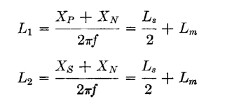
The value of k is never greater than unity, even when coils are interleaved to the maximum possible extent. Values of k down to 0.01 or lower are common at high frequencies. Coupling coefficient is related to untuned transformer open- and short-circuit reactance by means of the transformer equivalent circuit shown in Fig. 107(a), p. 147. Assume that the transformer has a 1:1 ratio, and leakage inductance is equally divided between primary and secondary windings. Then if L1 and L2 are the self-inductances of primary and secondary, respectively, Ls is the total leakage inductance (measured in the primary with secondary short-circuited), and Lm the mutual inductance,
From equation 104,
If Lm >> Ls
Equations 104 (a) and (b) are useful in estimating approximate transformer band width. A tuned air-core transformer often used in receivers is shown in Fig. 172.
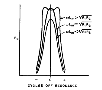
Here a sinusoidal voltage E1 may be impressed on the primary circuit by a vacuum tube amplifier. Resistances R1 and R2 are usually the inevitable resistance of coils, but occasionally resistance is added to change the circuit response. The value of voltage E2 obtained from this circuit depends on the impressed frequency; in Fig. 173 it is shown for resonance at three different values of coupling. If the value of coupling is such that
we obtain a condition similar to that of equation 103, in which the maximum power or current is produced in the secondary circuit. Maximum current through condenser C2 gives maximum voltage E2. This value of coupling is known as the critical value. Smaller coefficient of coupling gives a smaller maximum value of E2. Greater coefficient of coupling results in a "double hump" as shown in Fig. 173.
The heights of resonant peaks and frequency distance between peaks depend upon circuit Q and coefficient of coupling k. The double hump curve of Fig. 173 is desirable because, with modulated waves, frequencies in adjacent channels are rejected; yet very little attenuation is offered to audio frequencies which effectively add or subtract from the carrier frequency normally corresponding to resonance. Close tuning control and high Q are essential to good response and selectivity. If the primary circuit is made to resonate at a different frequency from the secondary, audio response is much worse, and considerable distortion is likely. Moreover, the response at mean frequency is less than it would be if the circuits were properly tuned. Air-core transformers are usually made adjustable for tuning and coupling.
|
||||||||||||||||||||||||
Home  Higher-Frequency Transformers Higher-Frequency Transformers  Air-Core Transformers Air-Core Transformers |
||||||||||||||||||||||||
Last Update: 2011-01-24


