| Electronic Transformers and Circuits is a free introductory textbook on transformers and related circuits. See the editorial for more information.... |

|

Home  Pulse Circuits Pulse Circuits  Sweep Generators Sweep Generators |
|||||||||||||||||||


|
|||||||||||||||||||
Sweep Generators
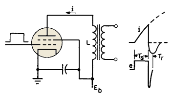
Pulses of sweep duration τs applied to the grid of a beam tetrode cause plate current to increase throughout the pulse. If the transformer had no losses, a pulse of constant amplitude Ea would cause current to increase linearly with time until the pulse ended, in accordance with equation 40:
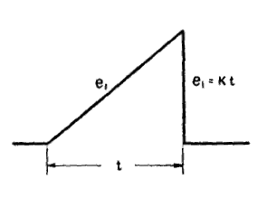
Losses in a practical transformer are equivalent to a resistance in series with L, and the rise in current is exponential. If the losses are small, current rise may be confined to the part of the exponential curve which is nearly linear, as indicated at the right in Fig. 257. The transformer load is usually the deflection coil of a picture tube. If this coil also has sufficiently low loss, the deflection coil current has the same wave form as the transformer primary, and a linear sweep results. At the end of the pulse, current i does not stop flowing immediately, because of the transformer and deflection coil inductance. A large voltage backswing amplitude results, corresponding to large values of A in Fig. 235. Values of L, C, and Re are such that the backswing is oscillatory with a period 2τr which is small compared to sweep duration τs. During τr, the first or negative half of the backswing oscillation, the oscilloscope beam is usually "blanked" or cut off quickly, to allow the beam to retrace to the extreme left, ready for the next sweep period. For a bright picture, the retrace period τr should be short compared to τs, so that scanning occurs during a large percentage of the time. In television receivers, the sweep frequency is 15,750 cycles and the backswing frequency approximately 77,000 cycles. Thus the retrace time is about 10 per cent of the sweep period. Positive voltage backswing is used in starting the next sweep trace, as will be described later. Magnetic deflection sweep transformers are made with low-loss cores. Manganese-zinc ferrites find wide use here. Design of sweep transformers is closely integrated with the sweep circuit, as will be shown in the next section. Electrostatic deflection is accomplished by application of sawtooth voltages to the horizontal plates of an oscilloscope. Such a voltage is shown in Fig. 258.
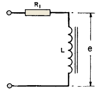
Sawtooth voltages may be formed in several ways from repetitive pulses.(1) If the pulse requires amplification before being applied to the tube plates, a sweep amplifier is necessary. Here again linearity is important. The spot is moved at a uniform rate across the screen and quickly returned to repeat the trace. In such a circuit, the load on the transformer can be regarded as negligible. Assume a linearly increasing voltage as shown in Fig. 258 to be applied to the equivalent circuit of Fig. 259.
e1 = Kt Then Lpe1 = LK where p = d( )/dt, and the voltage across the transformer primary is
Slope of e is
Thus voltage e has the same slope as the applied voltage times an exponential term which is determined by the resistance R1 of the amplifier, the OCL of the transformer, and the time between the beginning and the end of the linear sweep. Under the conditions assumed, the value of the exponential for any interval of time can be taken from the curve marked R2 = ∞ in Fig. 234. For example, suppose that the sweep lasts for 500 microseconds, that the sweep amplifier tube plate resistance is 800 ohms, and that the transformer inductance is 10 henrys. The abscissa of Fig. 234 is 0.04, and. since the slope of this exponential curve equals its ordinate, the slope of the voltage applied to the plates of the oscilloscope will be, at the end of the sawtooth interval, 96 per cent of the slope which it had at the beginning of the interval. Assume that at the end of the time interval t (Fig. 258) the amplifier tube is cut off. Then the sweep circuit transformer reverts to that of Fig. 235, in which CD has the same meaning as before but RI includes only the losses of the transformer, which were neglected in the analysis for linearity of sweep. That is to say, the voltage does not immediately disappear but follows the curves of Fig. 235 very closely, as in magnetic deflection. Backswing voltage may be kept from affecting the screen by suitable spacing of the applied wave forms or biasing the cathode-ray tube grid. Vertical sweep transformers are used in television receivers to displace the horizontal sweep lines at a 60-cycle rate, in order to produce a picture. The vertical displacement is fairly linear, retrace rapid, and sawtooth wave form is necessary here also. Because of the relatively slow vertical displacement, yoke inductance is negligible, so that vertical sweep amplifiers effectively operate into resistive loads during trace periods. The transformers present no particularly difficult problem beyond that of high OCL at low cost.
|
|||||||||||||||||||
Home  Pulse Circuits Pulse Circuits  Sweep Generators Sweep Generators |
|||||||||||||||||||
Last Update: 2011-02-17


