| The ebook FEEE - Fundamentals of Electrical Engineering and Electronics is based on material originally written by T.R. Kuphaldt and various co-authors. For more information please read the copyright pages. |

|
Home  Semiconductors Bipolar Junction Transistors The transistor as a switch Semiconductors Bipolar Junction Transistors The transistor as a switch |
||||


|
  |
|||
|
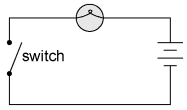
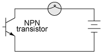
The transistor as a switchBecause a transistor's collector current is proportionally limited by its base current, it can be used as a sort of current-controlled switch. A relatively small flow of electrons sent through the base of the transistor has the ability to exert control over a much larger flow of electrons through the collector. Suppose we had a lamp that we wanted to turn on and off by means of a switch. Such a circuit would be extremely simple:
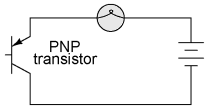
In this example I happened to choose an NPN transistor. A PNP transistor could also have been chosen for the job, and its application would look like this:
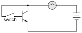
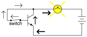
The choice between NPN and PNP is really arbitrary. All that matters is that the proper current directions are maintained for the sake of correct junction biasing (electron flow going against the transistor symbol's arrow). Going back to the NPN transistor in our example circuit, we are faced with the need to add something more so that we can have base current. Without a connection to the base wire of the transistor, base current will be zero, and the transistor cannot turn on, resulting in a lamp that is always off. Remember that for an NPN transistor, base current must consist of electrons flowing from emitter to base (against the emitter arrow symbol, just like the lamp current). Perhaps the simplest thing to do would be to connect a switch between the base and collector wires of the transistor like this:
If the switch is open, the base wire of the transistor will be left "floating" (not connected to anything) and there will be no current through it. In this state, the transistor is said to be cutoff. If the switch is closed, however, electrons will be able to flow from the emitter through to the base of the transistor, through the switch and up to the left side of the lamp, back to the positive side of the battery. This base current will enable a much larger flow of electrons from the emitter through to the collector, thus lighting up the lamp. In this state of maximum circuit current, the transistor is said to be saturated.
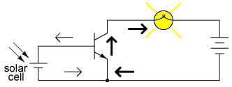
Of course, it may seem pointless to use a transistor in this capacity to control the lamp. After all, we're still using a switch in the circuit, aren't we? If we're still using a switch to control the lamp -- if only indirectly -- then what's the point of having a transistor to control the current? Why not just go back to our original circuit and use the switch directly to control the lamp current? There are a couple of points to be made here, actually. First is the fact that when used in this manner, the switch contacts need only handle what little base current is necessary to turn the transistor on, while the transistor itself handles the majority of the lamp's current. This may be an important advantage if the switch has a low current rating: a small switch may be used to control a relatively high-current load. Perhaps more importantly, though, is the fact that the current-controlling behavior of the transistor enables us to use something completely different to turn the lamp on or off. Consider this example, where a solar cell is used to control the transistor, which in turn controls the lamp:
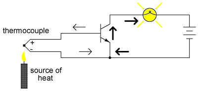
Or, we could use a thermocouple to provide the necessary base current to turn the transistor on:
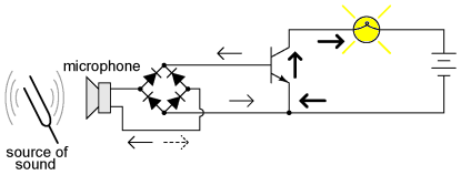
Even a microphone of sufficient voltage and current output could be used to turn the transistor on, provided its output is rectified from AC to DC so that the emitter-base PN junction within the transistor will always be forward-biased:
The point should be quite apparent by now: any sufficient source of DC current may be used to turn the transistor on, and that source of current need only be a fraction of the amount of current needed to energize the lamp. Here we see the transistor functioning not only as a switch, but as a true amplifier: using a relatively low-power signal to control a relatively large amount of power. Please note that the actual power for lighting up the lamp comes from the battery to the right of the schematic. It is not as though the small signal current from the solar cell, thermocouple, or microphone is being magically transformed into a greater amount of power. Rather, those small power sources are simply controlling the battery's power to light up the lamp.
|
||||
| Home Semiconductors Bipolar Junction Transistors The transistor as a switch |
|
|||
Last Update: 2010-12-01