| The ebook FEEE - Fundamentals of Electrical Engineering and Electronics is based on material originally written by T.R. Kuphaldt and various co-authors. For more information please read the copyright pages. |

|
Home  AC AC Motors Synchronous Motors Reluctance motor AC AC Motors Synchronous Motors Reluctance motor |
|


|
  |
|
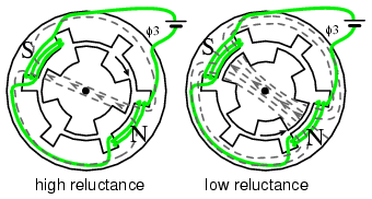
Reluctance motorThe variable reluctance motor is based on the principle that an unrestrained piece of iron will move to complete a magnetic flux path with minimum reluctance, the magnetic analog of electrical resistance. Synchronous reluctanceIf the rotating field of a large synchronous motor with salient poles is de-energized, it will still develop 10 or 15% of synchronous torque. This is due to variable reluctance throughout a rotor revolution. There is no practical application for a large synchronous reluctance motor. However, it is practical in small sizes. If slots are cut into the conductorless rotor of an induction motor, corresponding to the stator slots, a synchronousreluctance motor results. It starts like an induction motor but runs with a small amount of synchronous torque. The synchronous torque is due to changes in reluctance of the magnetic path from the stator through the rotor as the slots align. This motor is an inexpensive means of developing a moderate synchronous torque. Low power factor, low pull-out torque, and low efficiency are characteristics of the direct power line driven variable reluctance motor. Such was the status of the variable reluctance motor for a century before the development of semiconductor power control. Switched reluctanceIf an iron rotor with poles, but without any conductors, is fitted to a multi-phase stator, a switched reluctance motor, capable of synchronizing with the stator field results. When a stator coil pole pair is energized, the rotor will move to the lowest magnetic reluctance path. A switched reluctance motor is also known as a variable reluctance motor.
Sequential switching of the stator phases moves the rotor from one position to the next. The mangetic flux seeks the path of least reluctance, the magnetic analog of electric resistance.
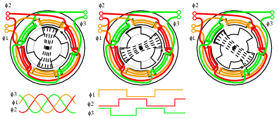
One end of each 3-phase winding of a switched reluctance motor is usually brought out via a common power supply wire, above left. The other coil connections are successively pulled to ground, one at a time, in a wave drive pattern. This attracts the rotor to the counterclockwise rotating magnetic field, above center, in 30o increments. Above right, double the number of poles decreases the rotating speed. A variable reluctance motor intended to move in discrete steps, stop, and start is a variable reluctance stepper motor, covered in another section. If smooth rotation is the goal, there is an electronic driven version of the switched reluctance motor. Electronic driven variable reluctance motorVariable reluctance motors are poor performers when direct power line driven. However, microprocessors and solid state power drive makes this motor an economical high performance solution in some high volume applications. Though difficult to control, this motor is easy to spin. Sequential switching of the field coils creates a rotating magnetic field which drags the irregularly shaped rotor around with it as it seeks out the lowest magnetic reluctance path. The relationship between torque and stator current is highly nonlinear-- difficult to control.
While the variable reluctance motor is simple, even more so than an induction motor, it is difficult to control. Electronic control solves this problem and makes it practical to drive the motor well above and below the power line frequency. A variable reluctance motor driven by a servo, an electronic feedback system, controls torque and speed, minimizing ripple torque.
This is the opposite of the high ripple torque desired in stepper motors. Rather than a stepper, a variable reluctance motor is optimized for continuous high speed rotation with minimum ripple torque. It is necessary to measure the rotor position with a rotary position sensor like an optical encoder, or derive this from monitoring the stator back EMF. A microprocessor performs complex calculations for switching the windings at the proper time with solid state devices. This must be done precisely to minimize audible noise and ripple torque. For lowest ripple torque, winding current must be monitored and controlled. The strict drive requirements make this motor only practical for high volume applications like energy efficient vacuum cleaner motors, fan motors, pump motors. One such vacuum cleaner uses a compact high efficiency electronic driven 100,000 rpm fan motor. The simplicity of the motor compensates for the drive electronics cost. No brushes, no commutator, no rotor windings, no permanent magnets, simplifies motor manufacture. The efficiency of this electronic driven motor can be high. But, it requires considerable optimization, using specialized design techniques, which is only justified for large manufacturing volumes. Advantages
|
|
| Home AC AC Motors Synchronous Motors Reluctance motor |
|


Last Update: 2010-11-19