| The ebook FEEE - Fundamentals of Electrical Engineering and Electronics is based on material originally written by T.R. Kuphaldt and various co-authors. For more information please read the copyright pages. |

|
Home  AC AC Motors Polyphase Induction Motors Theory of operation AC AC Motors Polyphase Induction Motors Theory of operation |
|


|
  |
|
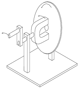
Theory of operationA short explanation of operation is that the stator creates a rotating magnetic field which drags the rotor around. The theory of operation of induction motors is based on a rotating magnetic field. One means of creating a rotating magnetic field is to rotate a permanent magnet as shown below. If the moving magnetic lines of flux cut a conductive disk, it will follow the motion of the magnet. The lines of flux cutting the conductor will induce a voltage, and consequent current flow, in the conductive disk. This current flow creates an electromagnet whose polarity opposes the motion of the permanent magnet-- Lenz's Law. The polarity of the electromagnet is such that it pulls against the permanent magnet. The disk follows with a little less speed than the permanent magnet.
The torque developed by the disk is proportional to the number of flux lines cutting the disk. If the disk were to spin at the same rate as the permanent magnet, there would be no flux cutting the disk, no induced current flow, no electromagnet field, no torque. Thus, the disk speed will always fall behind that of the rotating permanent magnet, so that lines of flux cut the disk induce a current, create an electromagnetic field in the disk, which follows the permanent magnet. If a load is applied to the disk slowing it, more torque will be developed. Torque is proportional to slip, the degree to which the disk falls behind the rotating magnet. More slip corresponds to more flux cutting the conductive disk. An analog automotive eddy current speedometer is based on the principle illustrated above. With the disk restrained by a spring, disk and needle deflection is proportional to magnet rotation rate. A rotating magnetic field is created by two coils placed at right angles to each other, driven by currents which are 90o out of phase. This should not be surprising if you are familiar with oscilloscope Lissajous patterns.
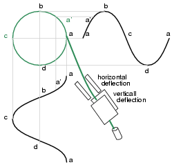
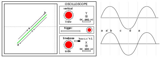
Above a circular Lissajous is produced by driving the horizontal and vertical oscilloscope inputs with 90o out of phase sine waves. Starting at (a) with maximum "X" and minimum "Y" deflection, the trace moves up and left toward (b). Between (a) and (b) the two waveforms are equal to 0.707 Vpk at 45o. This point (0.707, 0.707) falls on the radius of the circle between (a) and (b) The trace moves to (b) with minimum "X" and maximum "Y" deflection. With maximum negative "X" and minimum "Y" deflection, the trace moves to (c). Then with minimum "X" and maximum negative "Y", it moves to (d), and on back to (a), completing one cycle.
Above we illustrate that the two 90o phase shifted sine waves are applied to oscilloscope deflection plates which are at right angles in space. If this were not the case, a one dimensional line would display. The combination of 90o phased sine waves and right angle deflection, results in a two dimensional pattern-- a circle. This circle is traced out by a counterclockwise rotating spot. Below for reference, we show why in-phase sine waves will not produce a circular pattern. Equal "X" and "Y" deflection moves the illuminated spot from the origin at (a) up to right (1,1) at (b), back down left to origin at (c),down left to (-1.-1) at (d), and back up right to origin. The line is produced by equal deflections along both axes; y=x is a straight line.
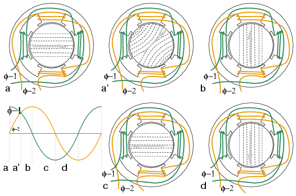
If a pair of 90o out of phase sine waves produces a circular Lissajous, a similar pair of currents should be able to produce a circular rotating magnetic field. Such is the case of a 2-phase motor. By analogy three windings placed 120o apart in space, and fed with corresponding 120o phased currents will also produce a rotating magnetic field.
As the 90o phased sinewaves, above left, progress from points (a) through (d), the magnetic field rotates counterclockwise (figures a-d) as follows:
Motor speedThe rotation rate of rotating magnetic field is related to the number of pole pairs per stator phase. The "full speed" figure below has a total of six poles or three pole-pairs and three phases. There it but one pole pair per phase-- the number we need. The magnetic field will rotate once per sine wave cycle. In the case of 60 Hz power, the field rotates at 60 times per second or 3600 revolutions per minute (rpm). For 50 Hz power, it rotates at 50 rotations per second, or 3000 rpm. The 3600 and 3000 rpm, are the synchronous speed of the motor. Though the rotor of an induction motor never achieves this speed, it certainly is an upper limit. If we double the number of motor poles, the synchronous speed is cut in half because the magnetic field rotates 180oin space for 360oelectrical sine wave.
The synchronous speed is given by: Ns = 120f/P Ns = synchronous speed in rpm f = frequency of applied power, Hz P = total number of poles per phase, a multiple of 2 Example: The above half "speed figure" has four poles per phase (3-phase). The synchronous speed for 50 Hz power is: S = 120*50/4 = 1500 rpm The short explanation of the induction motor is that the rotating magnetic field produced by the stator drags the rotor around with it. The longer more correct explanation is that the stator's magnetic field induces an alternating current into the rotor squirrel cage conductors which constitutes a transformer secondary. This induced rotor current in turn creates a magnetic field. The rotating stator magnetic field interacts with this rotor field. The rotor field attempts to align with the rotating stator field. The result is rotation of the squirrel cage rotor. If there were no mechanical motor torque load, no bearing, windage, or other losses, the rotor would rotate at the synchronous speed. However, the slip between the rotor and the synchronous speed stator field develops torque. It is the magnetic flux cutting the rotor conductors as it slips which develops torque. Thus, a loaded motor will slip in proportion to the mechanical load. If the rotor were to run at synchronous speed, there would be no stator flux cutting the rotor, no current induced in the rotor, no torque. TorqueWhen power is first applied to the motor, the rotor is at rest, while the stator magnetic field rotates at the synchronous speed Ns. The stator field is cutting the rotor at the synchronous speed Ns. The current induced in the rotor shorted turns is maximum, as is the frequency of the current, the line frequency. As the rotor speeds up, the rate at which stator flux cuts the rotor is the difference between synchronous speed Ns and actual rotor speed N, or (Ns - N). The ratio of actual flux cutting the rotor to synchronous speed is defined as slip: s = (Ns - N)/(Ns where Ns = synchronous speed, N = rotor speed The frequency of the current induced into the rotor conductors is only as high as the line frequency at motor start, decreasing as the rotor approaches synchronous speed. Rotor frequency is given by: fr = sf where s = slip, f = stator power line frequency Slip at 100% torque is typically 5% or less in induction motors. Thus for f = 50 Hz line frequency, the frequency of the induced current in the rotor fr = 0.05*50 = 2.5 Hz. Why is it so low? The stator magnetic field rotates at 50 Hz. The rotor speed is 5% less. The rotating magnetic field is only cutting the rotor at 2.5 Hz. The 2.5 Hz is the difference between the synchronous speed and the actual rotor speed. If the rotor spins a little faster, at the synchronous speed, no flux will cut the rotor at all, fr = 0.
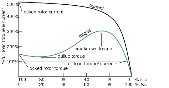
The above graph shows that starting torque known as locked rotor torque (LRT) is higher than 100% of the full load torque (FLT), the safe continuous torque rating. The locked rotor torque is about 175% of FLT for the example motor graphed above. Starting current known as locked rotor current (LRC) is 500% of full load current (FLC), the safe running current. The current is high because this is analogous to a shorted secondary on a transformer. As the rotor starts to rotate the torque may decrease a bit for certain classes of motors to a value known as the pull up torque. This is the lowest value of torque ever encountered by the starting motor. As the rotor gains 80% of synchronous speed, torque increases from 175% up to 300% of the full load torque. This breakdown torque is due to the larger than normal 20% slip. The current has decreased only slightly at this point, but will decrease rapidly beyond this point. As the rotor accelerates to within a few percent of synchronous speed, both torque and current will decrease substantially. Slip will be only a few percent during normal operation. For a running motor, any portion of the torque curve below 100% rated torque is normal. The motor load determines the operating point on the torque curve. While the motor torque and current may exceed 100% for a few seconds during starting, continuous operation above 100% can damage the motor. Any motor torque load above the breakdown torque will stall the motor. The torque, slip, and current will approach zero for a "no mechanical torque" load condition. This condition is analogous to an open secondary transformer. There are several basic induction motor designs showing consideable variation from the torque curve above. The different designs are optimized for starting and running different types of loads. The locked rotor torque (LRT) for various motor designs and sizes ranges from 60% to 350% of full load torque (FLT). Starting current or locked rotor current (LRC) can range from 500% to 1400% of full load current (FLC). This current draw can present a starting problem for large induction motors. NEMA design classesVarious standard classes (or designs) for motors, corresponding to the torque curves below have been developed to better drive various type loads. The National Electrical Manufacturers Association (NEMA) has specified motor classes A, B, C, and D to meet these drive requirements. Similar International Electrotechnical Commission (IEC) classes N and H correspond to NEMA B and C designs respectively.
All motors, except class D, operate at %5 slip or less at full load.
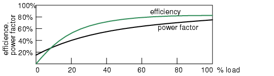
Power factorInduction motors present a lagging (inductive) power factor to the power line.The power factor in large fully loaded high speed motors can be as favorable as 90% for large high speed motors. At 3/4 full load the largest high speed motor power factor can be 92%. The power factor for small low speed motors can be as low as 50%. At starting, the power factor can be in the range of 10% to 25%, rising as the rotor achieves speed. Power factor (PF) varies considerably with the motor mechanical load. An unloaded motor is analogous to a transformer with no resistive load on the secondary. Little resistance is reflected from the secondary (rotor) to the primary (stator). Thus the power line sees a reactive load, as low as 10% PF. As the rotor is loaded an increasing resistive component is reflected from rotor to stator, increasing the power factor.
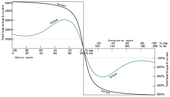
EfficiencyLarge three phase motors are more efficient than smaller 3-phase motors, and most all single phase motors. Large induction motor efficiency can be as high as 95% at full load, though 90% is more common. Efficiency for a lightly load or no-loaded induction motor is poor because most of the current is involved with maintaining magnetizing flux. As the torque load is increased, more current is consumed in generating torque, while current associated with magnetizing remains fixed. Efficiency at 75% FLT can be slightly higher than that at 100% FLT. Efficiency is decreased a few percent at 50% FLT, and decreased a few more percent at 25% FLT. Efficiency only becomes poor below 25% FLT. Most induction motors are typically oversized to guarantee that the mechanical load can be started and driven under all operating conditions. If the motor is loaded at less than 75% of rated torque where efficiency peaks, efficiency suffers only slightly down to 25% FLT. Nola power factor corrrectorFrank Nola of NASA proposed a power factor corrector as an energy saving device for single phase induction motors in the late 1970's. It is based on the premise that a less than fully loaded induction motor is less efficient and has a lower power factor than a fully loaded motor. Thus, there is energy to be saved in partially loaded motors, 1-Φ motors in particular. The energy consumed in maintaining the stator magnetic field is relatively fixed with respect to load changes. While there is nothing to be saved in a fully loaded motor, the voltage to a partially loaded motor may be reduced to decrease the energy required to maintain the magnetic field. This will increase power factor and efficiency. This was a good concept for the notoriously inefficient single phase motors for which it was intended. This concept is not very applicable to large 3-phase motors. Because of their high efficiency (90%+), there is not much energy to be saved. Moreover, a 95% efficient motor is still 94% efficient at 50% full load torque (FLT) and 90% efficient at 25% FLT. The potential energy savings in going from 100% FLT to 25% FLT is the difference in efficiency 95% - 90% = 5%. This is not 5% of the full load wattage but 5% of the wattage at the reduced load. The Nola power factor corrector might be applicable to a 3-phase motor which idles most of the time (below 25% FLT), like a punch press. The pay-back period for the expensive electronic controller has been estimated to be unattractive for most applications. Details: [*] Though, it might be economical as part of an electronic motor starter or speed Control. Induction motor alternatorAn induction motor may function as an alternator if it is driven by a torque at greater than 100% of the synchronous speed. This corresponds to a few % of "negative" slip, say -5% slip. This means that as we are rotating the motor faster than the synchronous speed, the rotor is advancing 5% faster than the stator rotating magnetic field. It normally lags by 5% in a motor. Since the rotor is cutting the stator magnetic field in the opposite direction (leading), the rotor induces a voltage into the stator feeding electrical energy back into the power line.
Such an induction generator must be excited by a "live" source of 50 or 60 Hz power. No power can be generated in the event of a power company power failure. This type of alternator appears to be unsuited as a standby power source. As an auxiliary power wind turbine generator, it has the advantage of not requiring an automatic power failure disconnect switch to protect repair crews. Start up procedure is to bring the wind turbine up to speed in motor mode by application of normal power line voltage to the stator. Any wind induced turbine speed in excess of synchronous speed will develop negative torque, feeding power back into the power line, reversing the normal direction of the electric kilowatt-hour meter. Whereas an induction motor presents a lagging power factor to the power line, an induction alternator presents a leading power factor. Induction generators are not widely used, even for wind turbines.
|
|
| Home AC AC Motors Polyphase Induction Motors Theory of operation |
|


Last Update: 2010-12-01