| The ebook FEEE - Fundamentals of Electrical Engineering and Electronics is based on material originally written by T.R. Kuphaldt and various co-authors. For more information please read the copyright pages. |

|
Home  AC AC Motors Wound rotor induction motors AC AC Motors Wound rotor induction motors |
|


|
  |
|
Wound rotor induction motorsA wound rotor induction motor has a stator like the squirrel cage induction motor, but a rotor with insulated windings brought out via slip rings and brushes. However, no power is applied to the slip rings. Their sole purpose is to allow resistance to be placed in series with the rotor windings while starting. This resistance is shorted out once the motor is started to make the rotor look electrically like the squirrel cage counterpart.
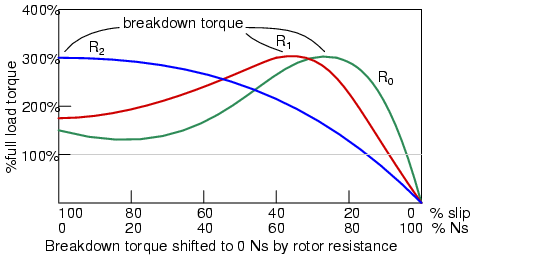
Why put resistance in series with the rotor? Squirrel cage induction motors draw 500% to over 1000% of full load current (FLC) during starting. While this is not a severe problem for small motors, it is for large (10's of Kw) motors. Placing resistance in series with the rotor windings not only decreases start current, locked rotor current (LRC), but also increases the starting torque, locked rotor torque (LRT). The figure above shows that by increasing the rotor resistance from R0 to R1 to R2, the breakdown torque peak is shifted left to zero speed.Note that this torque peak is much higher than the starting torque available with no rotor resistance (R0) Slip is proportional to rotor resistance, and pullout torque is proportional to slip. Thus, high torque is produced while starting.
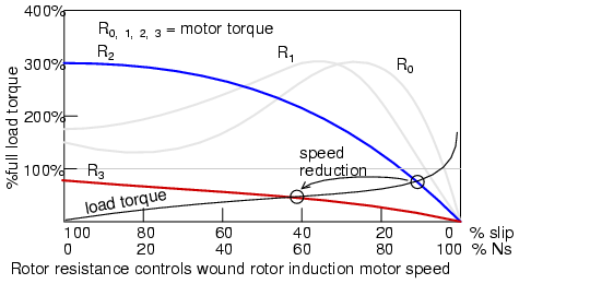
The resistance decreases the torque available at full running speed. But that resistance is shorted out by the time the rotor is started. A shorted rotor operates like a squirrel cage rotor. Heat generated during starting is mostly dissipated external to the motor in the starting resistance. The complication and maintenance associated with brushes and slip rings is a disadvantage of the wound rotor as compared to the simple squirrel cage rotor. This motor is suited for starting high inertial loads. A high starting resistance makes the high pull out torque available at zero speed. For comparison, a squirrel cage rotor only exhibits pull out (peak) torque at 80% of its' synchronous speed. Speed controlMotor speed may be varied by putting variable resistance back into the rotor circuit. This reduces rotor current and speed. The high starting torque available at zero speed, the down shifted break down torque, is not available at high speed. See R2 curve at 90% Ns, below. Resistors R0R1R2R3 increase in value from zero. A higher resistance at R3 reduces the speed further. Speed regulation is poor with respect to changing torque loads. This speed control technique is only usefull over a range of 50% to 100% of full speed. Speed control works well with variable speed loads like elevators and printing presses.
|
|
| Home AC AC Motors Wound rotor induction motors |
|

Last Update: 2010-11-19