| The ebook FEEE - Fundamentals of Electrical Engineering and Electronics is based on material originally written by T.R. Kuphaldt and various co-authors. For more information please read the copyright pages. |

|
Home  Digital Combinational Logic Encoder Digital Combinational Logic Encoder |
|||||||||||||||||||


|
  |
||||||||||||||||||
|
EncoderAn encoder is a circuit that changes a set of signals into a code. Let's begin making a 2-to-1 line encoder truth table by reversing the 1-to-2 decoder truth table.
This truth table is a little short. A complete truth table would be
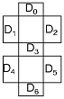
One question we need to answer is what to do with those other inputs? Do we ignore them? Do we have them generate an additional error output? In many circuits this problem is solved by adding sequential logic in order to know not just what input is active but also which order the inputs became active. A more useful application of combinational encoder design is a binary to 7-segment encoder. The seven segments are given according
Our truth table is:
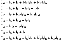
Deciding what to do with the remaining six entries of the truth table is easier with this circuit. This circuit should not be expected to encode an undefined combination of inputs, so we can leave them as "don't care" when we design the circuit. The boolean equations are
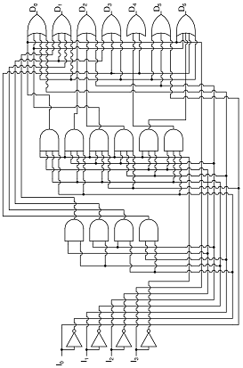
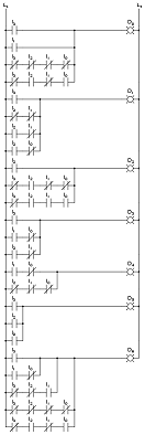
and the circuit is
|
|||||||||||||||||||
| Home Digital Combinational Logic Encoder |
|
||||||||||||||||||


Last Update: 2010-12-01