| The ebook FEEE - Fundamentals of Electrical Engineering and Electronics is based on material originally written by T.R. Kuphaldt and various co-authors. For more information please read the copyright pages. |

|
Home  Experiments Basic Concepts and Test Equipment Voltmeter usage Experiments Basic Concepts and Test Equipment Voltmeter usage |
|


|
  |
|
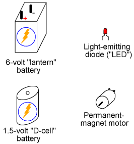
Voltmeter usagePARTS AND MATERIALS
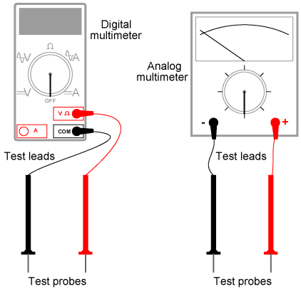
A multimeter is an electrical instrument capable of measuring voltage, current, and resistance. Digital multimeters have numerical displays, like digital clocks, for indicating the quantity of voltage, current, or resistance. Analog multimeters indicate these quantities by means of a moving pointer over a printed scale. Analog multimeters tend to be less expensive than digital multimeters, and more beneficial as learning tools for the first-time student of electricity. I strongly recommend purchasing an analog multimeter before purchasing a digital multimeter, but to eventually have both in your tool kit for these experiments.
CROSS-REFERENCES Lessons In Electric Circuits, Volume 1, chapter 1: "Basic Concepts of Electricity" Lessons In Electric Circuits, Volume 1, chapter 8: "DC Metering Circuits"
LEARNING OBJECTIVES
ILLUSTRATION
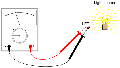
INSTRUCTIONS In all the experiments in this book, you will be using some sort of test equipment to measure aspects of electricity you cannot directly see, feel, hear, taste, or smell. Electricity -- at least in small, safe quantities -- is insensible by our human bodies. Your most fundamental "eyes" in the world of electricity and electronics will be a device called a multimeter. Multimeters indicate the presence of, and measure the quantity of, electrical properties such as voltage, current, and resistance. In this experiment, you will familiarize yourself with the measurement of voltage. Voltage is the measure of electrical "push" ready to motivate electrons to move through a conductor. In scientific terms, it is the specific energy per unit charge, mathematically defined as joules per coulomb. It is analogous to pressure in a fluid system: the force that moves fluid through a pipe, and is measured in the unit of the Volt (V). Your multimeter should come with some basic instructions. Read them well! If your multimeter is digital, it will require a small battery to operate. If it is analog, it does not need a battery to measure voltage. Some digital multimeters are autoranging. An autoranging meter has only a few selector switch (dial) positions. Manual-ranging meters have several different selector positions for each basic quantity: several for voltage, several for current, and several for resistance. Autoranging is usually found on only the more expensive digital meters, and is to manual ranging as an automatic transmission is to a manual transmission in a car. An autoranging meter "shifts gears" automatically to find the best measurement range to display the particular quantity being measured. Set your multimeter's selector switch to the highest-value "DC volt" position available. Autoranging multimeters may only have a single position for DC voltage, in which case you need to set the switch to that one position. Touch the red test probe to the positive (+) side of a battery, and the black test probe to the negative (-) side of the same battery. The meter should now provide you with some sort of indication. Reverse the test probe connections to the battery if the meter's indication is negative (on an analog meter, a negative value is indicated by the pointer deflecting left instead of right). If your meter is a manual-range type, and the selector switch has been set to a high-range position, the indication will be small. Move the selector switch to the next lower DC voltage range setting and reconnect to the battery. The indication should be stronger now, as indicated by a greater deflection of the analog meter pointer (needle), or more active digits on the digital meter display. For the best results, move the selector switch to the lowest-range setting that does not "over-range" the meter. An over-ranged analog meter is said to be "pegged," as the needle will be forced all the way to the right-hand side of the scale, past the full-range scale value. An over-ranged digital meter sometimes displays the letters "OL", or a series of dashed lines. This indication is manufacturer-specific. What happens if you only touch one meter test probe to one end of a battery? How does the meter have to connect to the battery in order to provide an indication? What does this tell us about voltmeter use and the nature of voltage? Is there such a thing as voltage "at" a single point? Be sure to measure more than one size of battery, and learn how to select the best voltage range on the multimeter to give you maximum indication without over-ranging. Now switch your multimeter to the lowest DC voltage range available, and touch the meter's test probes to the terminals (wire leads) of the light-emitting diode (LED). An LED is designed to produce light when powered by a small amount of electricity, but LEDs also happen to generate DC voltage when exposed to light, somewhat like a solar cell. Point the LED toward a bright source of light with your multimeter connected to it, and note the meter's indication:
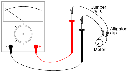
Batteries develop electrical voltage through chemical reactions. When a battery "dies," it has exhausted its original store of chemical "fuel." The LED, however, does not rely on an internal "fuel" to generate voltage; rather, it converts optical energy into electrical energy. So long as there is light to illuminate the LED, it will produce voltage. Another source of voltage through energy conversion a generator. The small electric motor specified in the "Parts and Materials" list functions as an electrical generator if its shaft is turned by a mechanical force. Connect your voltmeter (your multimeter, set to the "volt" function) to the motor's terminals just as you connected it to the LED's terminals, and spin the shaft with your fingers. The meter should indicate voltage by means of needle deflection (analog) or numerical readout (digital). If you find it difficult to maintain both meter test probes in connection with the motor's terminals while simultaneously spinning the shaft with your fingers, you may use alligator clip "jumper" wires like this:
Determine the relationship between voltage and generator shaft speed? Reverse the generator's direction of rotation and note the change in meter indication. When you reverse shaft rotation, you change the polarity of the voltage created by the generator. The voltmeter indicates polarity by direction of needle direction (analog) or sign of numerical indication (digital). When the red test lead is positive (+) and the black test lead negative (-), the meter will register voltage in the normal direction. If the applied voltage is of the reverse polarity (negative on red and positive on black), the meter will indicate "backwards."
|
|
| Home Experiments Basic Concepts and Test Equipment Voltmeter usage |
|
Last Update: 2011-03-21