| The ebook FEEE - Fundamentals of Electrical Engineering and Electronics is based on material originally written by T.R. Kuphaldt and various co-authors. For more information please read the copyright pages. |

|
Home  Experiments Discrete Semiconductor Circuits Full-wave bridge rectifier Experiments Discrete Semiconductor Circuits Full-wave bridge rectifier |
|


|
  |
|
Full-wave bridge rectifierExperiment: Bridge rectifierPARTS AND MATERIALS
CROSS-REFERENCES Lessons In Electric Circuits, Volume 3, chapter 3: "Diodes and Rectifiers"
LEARNING OBJECTIVES
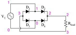
SCHEMATIC DIAGRAM
ILLUSTRATION
INSTRUCTIONS Split phaseThis circuit provides full-wave rectification without the necessity of a center-tapped transformer. In applications where a center-tapped, or split-phase, source is unavailable, this is the only practical method of full-wave rectification. In addition to requiring more diodes than the center-tap circuit, the full-wave bridge suffers a slight performance disadvantage as well: the additional voltage drop caused by current having to go through two diodes in each half-cycle rather than through only one. With a low-voltage source such as the one you're using (6 volts RMS), this disadvantage is easily measured. Compare the DC voltage reading across the motor terminals with the reading obtained from the last experiment, given the same AC power supply and the same motor.
COMPUTER SIMULATION
Fullwave bridge rectifier
v1 1 0 sin(0 8.485 60 0 0)
rload 2 3 10k
d1 3 1 mod1
d2 1 2 mod1
d3 3 0 mod1
d4 0 2 mod1
.model mod1 d
.tran .5m 25m
.plot tran v(1,0) v(2,3)
.end
|
|
| Home Experiments Discrete Semiconductor Circuits Full-wave bridge rectifier |
|


Last Update: 2011-03-21