| The ebook FEEE - Fundamentals of Electrical Engineering and Electronics is based on material originally written by T.R. Kuphaldt and various co-authors. For more information please read the copyright pages. |

|
Home  AC Filters Band-stop filters AC Filters Band-stop filters |
|||||
| See also: Band-pass filters, Resonant filters | |||||


|
  |
||||
|
Band-stop filtersAlso called band-elimination, band-reject, or notch filters, this kind of filter passes all frequencies above and below a particular range set by the component values. Not surprisingly, it can be made out of a low-pass and a high-pass filter, just like the band-pass design, except that this time we connect the two filter sections in parallel with each other instead of in series.
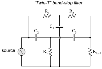
Constructed using two capacitive filter sections, it looks something like this:
The low-pass filter section is comprised of R1, R2, and C1 in a "T" configuration. The high-pass filter section is comprised of C2, C3, and R3 in a "T' configuration as well. Together, this arrangement is commonly known as a "Twin-T" filter, giving sharp response when the component values are chosen in the following ratios:
Given these component ratios, the frequency of maximum rejection (the "notch frequency") can be calculated as follows:
The impressive band-stopping ability of this filter is illustrated by the following SPICE analysis:
twin-t bandstop filter
v1 1 0 ac 1 sin
r1 1 2 200
c1 2 0 2u
r2 2 3 200
c2 1 4 1u
r3 4 0 100
c3 4 3 1u
rload 3 0 1k
.ac lin 20 200 1.5k
.plot ac v(3)
.end
|
|||||
| Home AC Filters Band-stop filters |
|
||||


Last Update: 2010-12-01