| The ebook FEEE - Fundamentals of Electrical Engineering and Electronics is based on material originally written by T.R. Kuphaldt and various co-authors. For more information please read the copyright pages. |

|
Home  AC Polyphase AC Circuits Three-phase transformer circuits AC Polyphase AC Circuits Three-phase transformer circuits |
|


|
  |
|
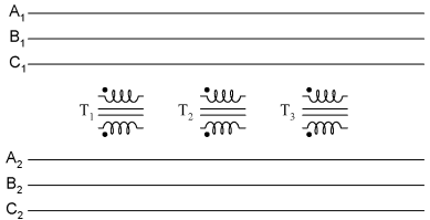
Three-Phase Transformer CircuitsSince three-phase is used so often for power distribution systems, it makes sense that we would need three-phase transformers to be able to step voltages up or down. This is only partially true, as regular single-phase transformers can be ganged together to transform power between two three-phase systems in a variety of configurations, eliminating the requirement for a special three-phase transformer. However, special three-phase transformers are built for those tasks, and are able to perform with less material requirement, less size, and less weight from their modular counterparts. A three-phase transformer is made of three sets of primary and secondary windings, each set wound around one leg of an iron core assembly. Essentially it looks like three single-phase transformers sharing a joined core:
Those sets of primary and secondary windings will be connected in either Δ or Y configurations to form a complete unit. The various combinations of ways that these windings can be connected together in will be the focus of this section. Whether the winding sets share a common core assembly or each winding pair is a separate transformer, the winding connection options are the same:
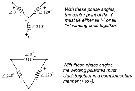
The reasons for choosing a Y or Δ configuration for transformer winding connections are the same as for any other three-phase application: Y connections provide the opportunity for multiple voltages, while Δ connections enjoy a higher level of reliability (if one winding fails open, the other two can still maintain full line voltages to the load). Probably the most important aspect of connecting three sets of primary and secondary windings together to form a three-phase transformer bank is attention to proper winding phasing (the dots used to denote "polarity" of windings). Remember the proper phase relationships between the phase windings of Δ and Y:
Getting this phasing correct when the windings aren't shown in regular Y or Δ configuration can be tricky. Let me illustrate:
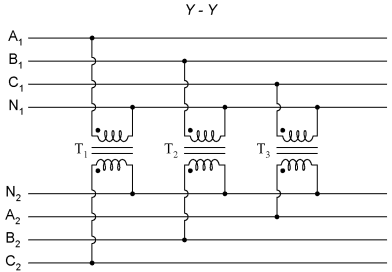
Three individual transformers are to be connected together to transform power from one three-phase system to another. First, I'll show the wiring connections for a Y-Y configuration:
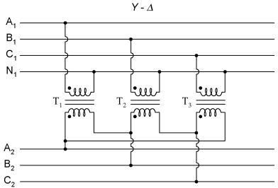
Note how all the winding ends marked with dots are connected to their respective phases A, B, and C, while the non-dot ends are connected together to form the centers of each "Y". Having both primary and secondary winding sets connected in "Y" formations allows for the use of neutral conductors (N1 and N2) in each power system. Now, we'll take a look at a Y-Δ configuration:
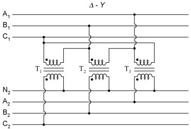
Note how the secondary windings (bottom set) are connected in a chain, the "dot'" side of one winding connected to the "non-dot" side of the next, forming the Δ loop. At every connection point between pairs of windings, a connection is made to a line of the second power system (A, B, and C). Now, let's examine a Δ-Y system:
Such a configuration would allow for the provision of multiple voltages (line-to-line or line-to-neutral) in the second power system, from a source power system having no neutral. And finally, we turn to the Δ-Δ configuration:
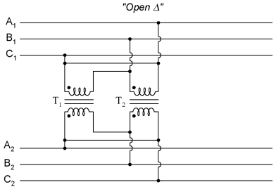
When there is no need for a neutral conductor in the secondary power system, Δ-Δ connection schemes are preferred because of the inherent reliability of the Δ configuration. Considering that a Δ configuration can operate satisfactorily missing one winding, some power system designers choose to create a three-phase transformer bank with only two transformers, representing a Δ-Δ configuration with a missing winding in both the primary and secondary sides:
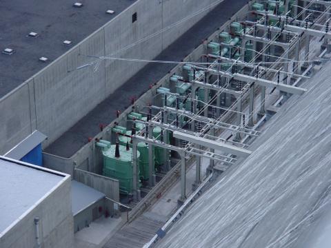
This configuration is called "V" or "Open-Δ." Of course, each of the two transformers have to be oversized to handle the same amount of power as three in a standard Δ configuration, but the overall size, weight, and cost advantages are often worth it. Bear in mind, however, that with one winding set missing from the Δ shape, this system no longer provides the fault tolerance of a normal Δ-Δ system. If one of the two transformers were to fail, the load voltage and current would definitely be affected. The following photograph shows a bank of step-up transformers at the Grand Coulee hydroelectric dam in Washington state. Several transformers (green in color) may be seen from this vantage point, and they are grouped in threes: three transformers per hydroelectric generator, wired together in some form of three-phase configuration. The photograph doesn't reveal the primary winding connections, but it appears the secondaries are connected in a Y configuration, being that there is only one large high-voltage insulator protruding from each transformer. This suggests the other side of each transformer's secondary winding is at or near ground potential, which could only be true in a Y system. The building to the left is the powerhouse, where the generators and turbines are housed. On the right, the sloping concrete wall is the downstream face of the dam:
|
|
| Home AC Polyphase AC Circuits Three-phase transformer circuits |
|


Last Update: 2011-03-21