| The ebook FEEE - Fundamentals of Electrical Engineering and Electronics is based on material originally written by T.R. Kuphaldt and various co-authors. For more information please read the copyright pages. |

|
Home  DC Series and Parallel Circuits Simple parallel circuits DC Series and Parallel Circuits Simple parallel circuits |
||||


|
  |
|||
|
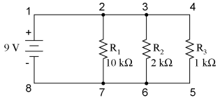
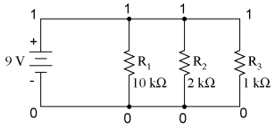
Simple parallel circuitsLet's start with a parallel circuit consisting of three resistors and a single battery:
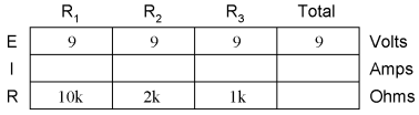
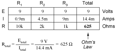
The first principle to understand about parallel circuits is that the voltage is equal across all components in the circuit. This is because there are only two sets of electrically common points in a parallel circuit, and voltage measured between sets of common points must always be the same at any given time. Therefore, in the above circuit, the voltage across R1 is equal to the voltage across R2 which is equal to the voltage across R3 which is equal to the voltage across the battery. This equality of voltages can be represented in another table for our starting values:
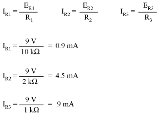
Just as in the case of series circuits, the same caveat for Ohm's Law applies: values for voltage, current, and resistance must be in the same context in order for the calculations to work correctly. However, in the above example circuit, we can immediately apply Ohm's Law to each resistor to find its current because we know the voltage across each resistor (9 volts) and the resistance of each resistor:
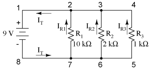
At this point we still don't know what the total current or total resistance for this parallel circuit is, so we can't apply Ohm's Law to the rightmost ("Total") column. However, if we think carefully about what is happening it should become apparent that the total current must equal the sum of all individual resistor ("branch") currents:
As the total current exits the negative (-) battery terminal at point 8 and travels through the circuit, some of the flow splits off at point 7 to go up through R1, some more splits off at point 6 to go up through R2, and the remainder goes up through R3. Like a river branching into several smaller streams, the combined flow rates of all streams must equal the flow rate of the whole river. The same thing is encountered where the currents through R1, R2, and R3 join to flow back to the positive terminal of the battery (+) toward point 1: the flow of electrons from point 2 to point 1 must equal the sum of the (branch) currents through R1, R2, and R3. This is the second principle of parallel circuits: the total circuit current is equal to the sum of the individual branch currents. Using this principle, we can fill in the IT spot on our table with the sum of IR1, IR2, and IR3:
Finally, applying Ohm's Law to the rightmost ("Total") column, we can calculate the total circuit resistance:
Please note something very important here. The total circuit resistance is only 625 Ω: less than any one of the individual resistors. In the series circuit, where the total resistance was the sum of the individual resistances, the total was bound to be greater than any one of the resistors individually. Here in the parallel circuit, however, the opposite is true: we say that the individual resistances diminish rather than add to make the total. This principle completes our triad of "rules" for parallel circuits, just as series circuits were found to have three rules for voltage, current, and resistance. Mathematically, the relationship between total resistance and individual resistances in a parallel circuit looks like this:
The same basic form of equation works for any number of resistors connected together in parallel, just add as many 1/R terms on the denominator of the fraction as needed to accommodate all parallel resistors in the circuit. Just as with the series circuit, we can use computer analysis to double-check our calculations. First, of course, we have to describe our example circuit to the computer in terms it can understand. I'll start by re-drawing the circuit:
Once again we find that the original numbering scheme used to identify points in the circuit will have to be altered for the benefit of SPICE. In SPICE, all electrically common points must share identical node numbers. This is how SPICE knows what's connected to what, and how. In a simple parallel circuit, all points are electrically common in one of two sets of points. For our example circuit, the wire connecting the tops of all the components will have one node number and the wire connecting the bottoms of the components will have the other. Staying true to the convention of including zero as a node number, I choose the numbers 0 and 1:
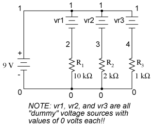
An example like this makes the rationale of node numbers in SPICE fairly clear to understand. By having all components share common sets of numbers, the computer "knows" they're all connected in parallel with each other. In order to display branch currents in SPICE, we need to insert zero-voltage sources in line (in series) with each resistor, and then reference our current measurements to those sources. For whatever reason, the creators of the SPICE program made it so that current could only be calculated through a voltage source. This is a somewhat annoying demand of the SPICE simulation program. With each of these "dummy" voltage sources added, some new node numbers must be created to connect them to their respective branch resistors:
The dummy voltage sources are all set at 0 volts so as to have no impact on the operation of the circuit. The circuit description file, or netlist, looks like this:
Parallel circuit
v1 1 0
r1 2 0 10k
r2 3 0 2k
r3 4 0 1k
vr1 1 2 dc 0
vr2 1 3 dc 0
vr3 1 4 dc 0
.dc v1 9 9 1
.print dc v(2,0) v(3,0) v(4,0)
.print dc i(vr1) i(vr2) i(vr3)
.end
Running the computer analysis, we get these results (I've annotated the printout with descriptive labels): v1 v(2) v(3) v(4) 9.000E+00 9.000E+00 9.000E+00 9.000E+00 battery R1 voltage R2 voltage R3 voltage voltage v1 i(vr1) i(vr2) i(vr3) 9.000E+00 9.000E-04 4.500E-03 9.000E-03 battery R1 current R2 current R3 current voltage These values do indeed match those calculated through Ohm's Law earlier: 0.9 mA for IR1, 4.5 mA for IR2, and 9 mA for IR3. Being connected in parallel, of course, all resistors have the same voltage dropped across them (9 volts, same as the battery). In summary, a parallel circuit is defined as one where all components are connected between the same set of electrically common points. Another way of saying this is that all components are connected across each other's terminals. From this definition, three rules of parallel circuits follow: all components share the same voltage; resistances diminish to equal a smaller, total resistance; and branch currents add to equal a larger, total current. Just as in the case of series circuits, all of these rules find root in the definition of a parallel circuit. If you understand that definition fully, then the rules are nothing more than footnotes to the definition.
|
||||
| Home DC Series and Parallel Circuits Simple parallel circuits |
|
|||


Last Update: 2010-12-01