| The ebook FEEE - Fundamentals of Electrical Engineering and Electronics is based on material originally written by T.R. Kuphaldt and various co-authors. For more information please read the copyright pages. |
|
Home  Experiments 555 Timer Circuits Hysteretic Oscillator Experiments 555 Timer Circuits Hysteretic Oscillator |
|


|
  |
|
Hysteretic OscillatorPARTS AND MATERIALS
CROSS-REFERENCES Lessons In Electric CircuitsVolume 1, chapter 16: Voltage and current calculations Lessons In Electric Circuits, Volume 1, chapter 16: Solving for unknown time Lessons In Electric Circuits, Volume 4, chapter 10: Multivibrators
Lessons in Electric Circuits, Volume 3, chapter 8: Positive Feedback
LEARNING OBJECTIVES
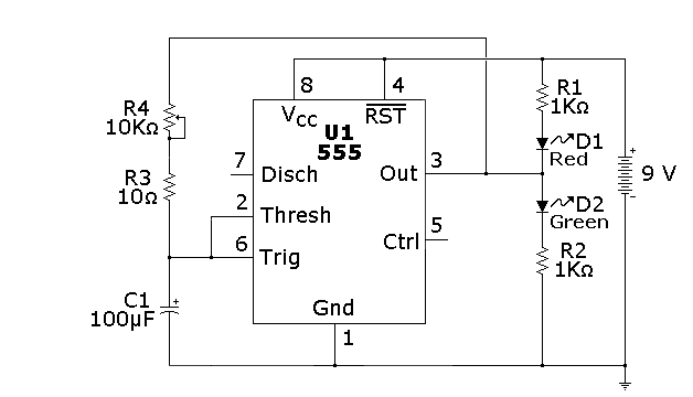
SCHEMATIC DIAGRAM Here is one way of drawing the schematic:
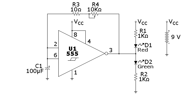
As mentioned in the previous experiment, there is also another convention, shown below:
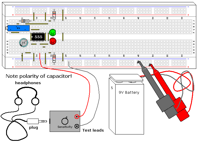
ILLUSTRATION
INSTRUCTIONS This is one of the most basic RC oscillators. It is simple and very predictable. Any inverting Schmitt Trigger will work in this design, although the frequency will shift somewhat depending on the hysteresis of the gate. This circuit has a lower end frequency of 0.7 Hertz, which means each LED will alternate and be lit for just under a second each. As you turn the potentiometer counterclockwise the frequency will increase, going well into the high end audio range. You can verify this with the Audio Detector (Vol. VI, Chapter 3, Section 12) or a piezoelectric speaker, as you continue to turn the potentiometer the pitch of the sound will rise. You can increase the frequency 100 times by replacing the capacitor with the 1µF capacitor, which will also raise the maximum frequency well into the ultrasonic range, around 70Khz. The 555 does not go rail to rail (it doesn't quite reach the upper supply voltage) because of its output Darlington transistors, and this causes the oscillators square wave to be not quite symmetrical. Can you see this looking at the LEDs? The higher the power supply voltage, the less pronounced this asymmetry is, while it gets worse with lower power supply voltages. If the output were true rail to rail it would be a 50% square wave, which can be attained if one uses the CMOS version of the 555, such as the TLC555 (Radio Shack P/N 276-1718). R3 was added to prevent shorting the IC output through C1, as the capacitor shorts the AC portion of the 555 output to ground. On a discharged battery it is not noticeable, but with a fresh 9V the 555 IC will get very hot. If you eliminate the resistor and adjust R4 for maximum frequency you can test this, it is not good for the battery or the 555, but they will survive a short test.
THEORY OF OPERATION This is a hysteretic oscillator, which is a type of relaxation oscillator. It is also an astable multivibrator. It is a logical offshoot of the 555 Schmitt Trigger experiment shown earlier. The formula to calculate the frequency with this configuration using a 555 is:
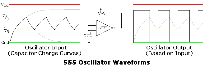
The 555 hysteresis is dependent on the supply voltage, so the frequency of the oscillator would be relatively independent of the supply voltage if it weren't for the lack of rail to rail output. The output of a 555 either goes to ground, or relatively close to the plus voltage. This allows the resistor and capacitor to charge and discharge through the output pin. Since this is a digital type signal, the LEDs interact very little in its operation. The first pulse generated by the oscillator is a bit longer than the rest. This and the charge/discharge curves are shown in the following illustration, which also shows why the asymmetrical square wave is created.
|
|
| Home Experiments 555 Timer Circuits Hysteretic Oscillator |
|

Last Update: 2011-03-21