| The ebook FEEE - Fundamentals of Electrical Engineering and Electronics is based on material originally written by T.R. Kuphaldt and various co-authors. For more information please read the copyright pages. |

|
Home  AC Transformers Practical Considerations Core saturation AC Transformers Practical Considerations Core saturation |
|


|
  |
|
Core saturationTransformers are also constrained in their performance by the magnetic flux limitations of the core. For ferromagnetic core transformers, we must be mindful of the saturation limits of the core. Remember that ferromagnetic materials cannot support infinite magnetic flux densities: they tend to "saturate" at a certain level (dictated by the material and core dimensions), meaning that further increases in magnetic field force (mmf) do not result in proportional increases in magnetic field flux (Φ). When a transformer's primary winding is overloaded from excessive applied voltage, the core flux may reach saturation levels during peak moments of the AC sinewave cycle. If this happens, the voltage induced in the secondary winding will no longer match the wave-shape as the voltage powering the primary coil. In other words, the overloaded transformer will distort the waveshape from primary to secondary windings, creating harmonics in the secondary winding's output. As we discussed before, harmonic content in AC power systems typically causes problems. Special transformers known as peaking transformers exploit this principle to produce brief voltage pulses near the peaks of the source voltage waveform. The core is designed to saturate quickly and sharply, at voltage levels well below peak. This results in a severely cropped sine-wave flux waveform, and secondary voltage pulses only when the flux is changing (below saturation levels):
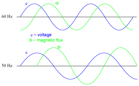
Another cause of abnormal transformer core saturation is operation at frequencies lower than normal. For example, if a power transformer designed to operate at 60 Hz is forced to operate at 50 Hz instead, the flux must reach greater peak levels than before in order to produce the same opposing voltage needed to balance against the source voltage. This is true even if the source voltage is the same as before.
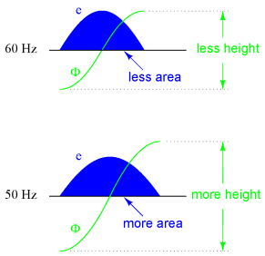
Since instantaneous winding voltage is proportional to the instantaneous magnetic flux's rate of change in a transformer, a voltage waveform reaching the same peak value, but taking a longer amount of time to complete each half-cycle, demands that the flux maintain the same rate of change as before, but for longer periods of time. Thus, if the flux has to climb at the same rate as before, but for longer periods of time, it will climb to a greater peak value. Mathematically, this is another example of calculus in action. Because the voltage is proportional to the flux's rate-of-change, we say that the voltage waveform is the derivative of the flux waveform, "derivative" being that calculus operation defining one mathematical function (waveform) in terms of the rate-of-change of another. If we take the opposite perspective, though, and relate the original waveform to its derivative, we may call the original waveform the integral of the derivative waveform. In this case, the voltage waveform is the derivative of the flux waveform, and the flux waveform is the integral of the voltage waveform. The integral of any mathematical function is proportional to the area accumulated underneath the curve of that function. Since each half-cycle of the 50 Hz waveform accumulates more area between it and the zero line of the graph than the 60 Hz waveform will -- and we know that the magnetic flux is the integral of the voltage -- the flux will attain higher values:
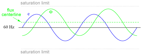
Yet another cause of transformer saturation is the presence of DC current in the primary winding. Any amount of DC voltage dropped across the primary winding of a transformer will cause additional magnetic flux in the core. This additional flux "bias" or "offset" will push the alternating flux waveform closer to saturation in one half-cycle than the other:
For most transformers, core saturation is a very undesirable effect, and it is avoided through good design: engineering the windings and core so that magnetic flux densities remain well below the saturation levels. This ensures that the relationship between mmf and Φ is more linear throughout the flux cycle, which is good because it makes for less distortion in the magnetization current waveform. Also, engineering the core for low flux densities provides a safe margin between the normal flux peaks and the core saturation limits to accommodate occasional, abnormal conditions such as frequency variation and DC offset.
|
|
| Home AC Transformers Practical Considerations Core saturation |
|

Last Update: 2010-12-01