| Practical Physics is a free textbook on basic laboratory physics. See the editorial for more information.... |

|
Home  Measurement of the More Simple Quantities Length The Kathetometer Measurement of the More Simple Quantities Length The Kathetometer |
||
| See also: The Spherometer | ||


|
  |
|
The Kathetometer
This instrument consists ot a vertical beam carrying a scale. Along the scale there slides a brass piece, supporting a telescope, the axis of which can be adjusted so as to be horizontal The brass slide is fitted with a vernier which reads fractions of the divisions of the scale, thus determining the position of the telescope.
Let us suppose the instrument to be in adjustment, and let p, Q be the two points, the vertical distance between which is required. The telescope of the instrument has, as usual, cross-wires in the eye-piece. Focus the telescope on the mark P, and adjust it until the image of P coincides with the horizontal cross-wire. Then read the scale and vernier. Let the reading be 72.125 cm. Raise the telescope until Q comes into the field, and adjust again till the image of Q coincides with the cross-wire; let the reading be 33.275 cm. The difference in level between P and Q is 72.125 - 33.275, or 38.850 cm. The adjustments are:
Vertical ScaleThe scale must be vertical, because we use the instrument to measure the vertical height between two points. The scale and level attached to it (fig. 5) can be turned round an axis which is vertical when properly adjusted, carrying the telescope with them, and can be clamped in any position by means of a screw.
(a) To test the Accuracy of the Setting of the Scale-level and to set the Axis of Rotation vertical. If the scale-level is properly set it is perpendicular to the axis of rotation; to ascertain whether or not this is so, turn the scale until its level is parallel to the line joining two of the foot-screws and clamp it; adjust these screws until the bubble of the level is in the middle. Unclamp, and turn the scale round through 180°. If the bubble is still in the middle of the level, it follows that this is at right angles to the axis of rotation; if the bubble has moved, then the level and the axis of rotation are not at right angles. We may make them so by adjusting the screws which, fix the level to the instrument until the rotation through 180° produces no change, or, without adjusting the level, we may proceed to set the axis of rotation vertical if, instead of adjusting the levelling screws of the instrument until the bubble stands in the centre of the tube, we adjust them until the bubble does not move relatively to the tube when the instrument is turned through 180°. This having been secured by the action of two of the screws, turn the scale until the level is at right angles to its former position and clamp. Adjust now in the same manner as before, using only the third screw. It follows then that the bubble will remain unaltered in position for all positions of the instrument, and that the axis about which it turns is vertical. If the scale of the instrument were parallel to the axis, it, too, would be vertical, and the instrument would be in adjustment (b) To set the Scale vertical. To do this there is provided a metallic bracket-piece. One arm of this carries a level, while the other is a flat surface at right angles to the axis of the level, so that when the level is horizontal this surface is truly vertical The adjustment can be tested in the following manner. The level can rotate about its axis, and is weighted so that the same part of the tube remains uppermost as the bracket is rotated about the axis of the level. Place then the flat face of the bracket with the level uppermost against a nearly vertical plane surface; notice the position of the bubble. Then reverse it so that the level is lowest, and read the position of the bubble again. If it has not changed the level is truly set, if any displacement has taken place it is not so. The scale of the instrument can be adjusted relatively to the axis of rotation and fixed by screws. Press the flat surface of the bracket-piece against the face of the scale. If the scale be vertical, the bubble of the level on the bracket-piece will occupy the middle of its tube. Should it not do so, the scale must be adjusted until the bubble comes to the central position. We are thus sure that the scale is vertical. For ordinary use, with a good instrument, this last adjustment may generally be taken as made. Now turn the telescope and, if necessary, raise or lower it until the object to be observed is nearly in the middle of the field of view.
Horizontal Telescope AxisIt is necessary that the axis of the telescope should be always inclined to the scale at the same angle, for if, when viewing a second point Q, the angle between the axis and the scale has changed from what it was in viewing P, it is clear that the distance through which the telescope has been displaced will not be the vertical distance between P and Q.If, however, the two positions of the axis be parallel, the difference of the scale readings will give us the distance we require. Now the scale itself is vertical. The safest method, therefore, of securing that the axis of the telescope shall be always inclined at the same angle to the scale is to adjust the telescope so that its axis shall be horizontal. The method of doing this will be different for different instruments. We shall describe that for the one at the Cavendish Laboratory in full detail; the plan to be adopted for other instruments will be some modification of this.
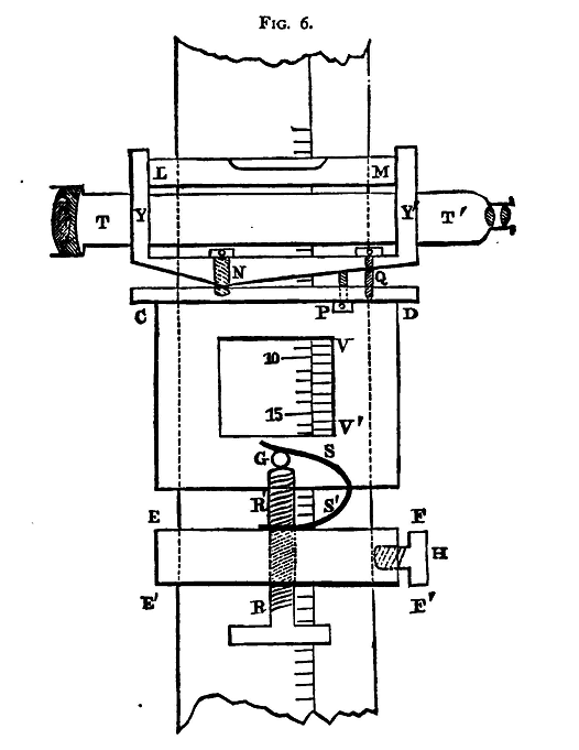
In this instrument (fig. 6) a level L M is attached to the telescope T T'. The telescope rests in a frame Y Y'. The lower side of this frame is bevelled slightly at N; the two surfaces Y N, Y' N being flat, but inclined to each other at an angle not far from 180°. This under side rests at N on a flat surface C D, which is part of the sliding-piece C D, to which the vernier V V' is fixed. A screw passes through the piece Y Y' at N, being fixed into C D. The hole in the piece Y Y' is large and somewhat conical, so that the telescope and its support can be turned about N, sometimes to bring N Y into contact with C N, sometimes to bring N Y' into contact with N D. Fitted into C D and passing freely through a hole in N Y' is a screw Q; P is another screw fitted into C D, which bears against N Y'. Hidden by P and therefore not shown in the figure is a third screw just like P, also fitted into C D, and bearing against N Y'. The screws N, P, and Q can all be turned by means of a tommy passed through the holes in their heads. When P and Q are both screwed home, the level and telescope are rigidly attached to the sliding-piece C D. Release somewhat the screw Q. If now we raise the two screws P, we raise the eye-piece end of the telescope, and the level-bubble moves towards that end. If we lower the screws P, we lower the eye-piece end, and the bubble moves in the opposite direction. Thus the telescope can be levelled by adjusting the screws P. Suppose the bubble is in the centre of the level. Screw down the screw Q. This will hold the telescope fixed in the horizontal position. If we screw Q too firmly down, we shall force the piece N Y' into closer contact with the screws P, and lower the eye-piece end. It will be better then to adjust the screw p so that the bubble is rather too near that end of the tube. Then screw down Q until it just comes to the middle of the tube, and the telescope is level.
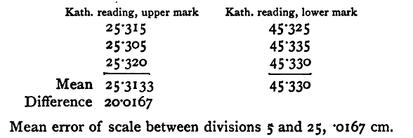
Coincide with Cross-WiresTo bring the image of the object viewed to coincide with the cross-wires.The piece C D slides freely up and down the scale. E F F'E' is another piece of brass which also slides up and down. H is a screw by means of which E F' can be clamped fast to the scale. A screw R R' passes vertically upwards through E F' and rests against the under side of a steel pin G fixed in C D. Fixed to E F' and pressing downwards on the pin G so as to keep it in contact with the screw R R' is a steel spring S S'. By turning the screw R R', after clamping H, a small motion up or down can be given to the sliding piece C D and telescope. Now loosen the screw H and raise or lower the two pieces C D, E F' together by hand, until the object viewed is brought nearly into the middle of the field of view. Then clamp E F' by the screw H. Notice carefully if this operation has altered the level of the telescope; if it has, the levelling must be done again. By means of the screw R R' raise or lower the telescope as may be needed until the image is brought into coincidence with the cross-wire. Note again if the bubble of the level is in its right position, and if so read the scale and vernier. It may happen that turning the screw R R' is sufficient to change the level of the telescope. In order that the slide c D may move easily along the scale, a certain amount of play must be left, and the friction between R' and the pin is sometimes sufficient to cause this play to upset the level adjustment. The instrument is on this account a troublesome one to use. The only course we can adopt is to level; and then adjust R R' till the telescope is in the right position, levelling again if the last operation has rendered it necessary. This alteration of level will produce a small change in the position of the line of collimation of the telescope relatively to the vernier, and thus introduce an error, unless the axis round which the telescope turns is perpendicular both to the line of collimation and to the scale. If, however, the axis is only slightly below the line of collimation and the change of level small, the error will be very small indeed and may safely be neglected. It is clear that the error produced by an error in levelling will be proportional to the distance between the instrument and the object whose height is being measured. We should therefore bring the instrument as close to the object as is possible. Experiment. - Adjust the kathetometer, and compare by means of it a length of 20 cm. of the given rule with the scale of the instrument. Hang the rule up at a suitable distance from the kathetometer, and measure the distance between division 5 cm. and 25 cm. The reading of the kathetometer scale in each position must be taken three times at least, the telescope being displaced by means of the screw R R' between each observation. Enter results as below:
|
||
| Home Measurement of the More Simple Quantities Length The Kathetometer |
|
|

Last Update: 2011-03-27