| Practical Physics is a free textbook on basic laboratory physics. See the editorial for more information.... |

|
Home  Mirrors and Lenses The Sextant Mirrors and Lenses The Sextant |
||


|
  |
|
The Sextant
The sextant consists of a graduated circular arc, B C (fig. 24), of about 60°, connected by two metal arms, A B, A C, with its centre A. A D is a third movable arm, which turns round an axis passing through the centre A, at right angles to the plane of the arc, and is fitted with a clamp and tangent screw. A vernier, is attached to this arm at D, and by means of it the position of the arm with reference to the scale can be determined. The vernier is generally constructed to read to 15".
A plane mirror, M, is attached to this arm and moves with it. The plane of the mirror passes through the centre of the circular arc and is at right angles to the plane of the scale. The mirror is known as the index glass, and is held by adjustable screws in a frame which is rigidly connected to the arm A D. By means of the screws it can be placed so that its plane is accurately perpendicular to that of the arc. At F on the arm A C is another mirror called the horizon glass, also secured by adjustable screws to the arm. Its plane should be perpendicular to that of the arc and parallel to that of the movable mirror M when the index at D stands at the zero of the scale. The upper half of the mirror F is left unsilvered.
The telescope is fitted with cross-wires, and by altering the position of the arm A D the image of P can be made to coincide with that of Q in the centre of the field of view. Let us suppose this adjustment made. Then by reflexion at the two mirrors the ray P A has been made to coincide in direction with the ray Q F. Hence, the angle between P A and Q F is twice the angle between the two mirrors. But when the index read zero the two mirrors were parallel, so that twice the angle between the two mirrors is twice the angle through which the arm and vernier have been turned from zero. In many instruments the graduations are numbered to read as double of their real value; each degree is reckoned as two degrees and so on, so that, if the instrument be in adjustment, the reading of the vernier gives us directly the angle between P A and Q F, that is, the angle which the two distant points P and Q subtend at the observer's eye. The requisite adjustments are:
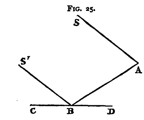
The two glasses are held in their frames by screws, and can be set in any position by altering these screws. (1) Place the eye close to the index glass and look towards the glass so as to see part of the arc CD and its reflexion, meeting at the surface of the glass. If the two, the arc and its image, appear to be in the same plane, then the glass is perpendicular to that plane. If, however, the image appears to rise out of the plane of the arc, the upper portion of the glass leans forward towards the eye, while if the image appears to drop below the plane of the arc, the glass leans back away from the eye. Adjust the screws' till the arc'and its image appear to be in the same plane; then the plane of the glass is at right angles to that plane. (2) To set the horizon glass. Hold the instrument so as to view directly with the telescope some distant point - a star if possible. On turning the index arm round, an image of the point, formed by reflexion at the two glasses, will cross the field. If the two glasses be accurately parallel, this image can be made to coincide exactly with the object seen by the direct rays. If the plane of the horizon glass . be not at right angles to that of the arc, so that the two mirrors can never be parallel, the image will appear to pass to one side or the other of the object. By altering the adjusting screws of the horizon glass, the image seen after two reflexions, and the object seen directly, can be made to coincide in position. When this is the case the two mirrors are strictly parallel, and the horizon glass, therefore, is at right angles to the plane of the arc. (3) To set the axis of the telescope parallel to the plane of the arc. For this it is necessary that the ring to which the telescope is fixed should be capable of being moved about an axis parallel to the line of intersection of its plane with that of the arc. The eye-piece of the telescope is usually fitted with two cross-wires, very approximately parallel to the plane of the arc, and one wire at right angles to these, passing through their middle points. The line joining the centre of the object glass to the middle point of this wire is the optical axis of the telescope. Hold the instrument so as to view two distant points, such as two stars, the one directly and the other by reflexion at the two glasses, and incline it to the plane through the eye and the two stars in such a way that the two images seen in the telescope appear to coincide at the point in which the third wire cuts one of the two parallel wires. Then, without moving the index glass, incline the plane of the instrument until the image of the star seen directly falls on the intersection of the third wire and the other of the two parallel wires. If the image of the second star again coincides with that of the first, it follows that the optical axis of the telescope is parallel to the plane of the arc; to make the two parallel the position of the telescope with reference to the arc must be adjusted until it is possible to observe such a coincidence. (4) To set the two mirrors parallel when the vernier-index reads zero. It will be found that one of the glasses with its frame and adjusting-screws can be moved about an axis at right angles to the plane of the arc. Set the vernier to read zero and clamp it, and direct the telescope to some distant point. If the two glasses are parallel this point, and its image after reflexion at the two mirrors, will appear to coincide. If they do not coincide they can be made to do so - supposing adjustments (1) and (2) have been made - by turning the movable mirror about the axis just spoken of, and when the coincidence is effected the mirrors will be parallel, while the vernier reads zero. Instead, however, of making this last adjustment, it is better to proceed as follows to determine the index error of the instrument Direct the telescope to a distant point and turn the index glass until the image of the point, after reflexion at the two mirrors, coincides with the point itself as seen directly. Clamp the vernier and read j let the reading be α. If the instrument were in perfect adjustment, the value of a would be zero. Suppose, now, we find that when proceeding to measure the angular distance between two distant points, as already described, the scale and vernier reading is β, then the angular distance required is β-α. Generally it gives less trouble to determine the index error than to set the mirrors so that there is no such error. It may, of course, happen that the value of a is negative - in other words, that to bring a point and its image into coincidence we have to push the vernier back beyond the zero of the scale; for this reason the scale graduations are continued beyond the zero. It is important for accurate work that the two images which are brought into coincidence should be about equally - bright. Now, the light from one has suffered two reflexions, each of which somewhat diminishes its intensity. If, then, the two distant objects are unequally bright, we should choose the duller one as that to be viewed directly. Again, we have said already that the telescope can be moved in a direction at right angles to the plane of the arc. In its normal position the axis of the telescope will pass through the boundary between the silvered and unsilvered parts of the horizon glass. Half the object-glass will accordingly be filled with direct light, half with reflected. If the direct light is very much stronger than the reflected, we can, by moving the telescope, still keeping its axis parallel to the plane of the circle, place it so that the reflected rays fill more than half and the direct rays less than half the object glass, and thus reduce the brightness of the direct and increase that of the reflected image. There are also shades of coloured glass attached to the instrument, which can be interposed in the path of either pencil and so decrease its intensity. The instrument is frequently used to observe the altitude of the sun or of a star; and in this case the horizon, if it is visible, forms one of the distant points, and when the instrument is adjusted, the image of the sun's lower limb should appear to coincide with this. If the horizon be not visible, an 'artificial horizon' is obtained by reflexion from some horizontal surface - that of pure mercury in a trough is most frequently used. For consider two parallel rays SA, S'B (fig. 25) coming from a distant object, and let S'B be reflected at B from a horizontal surface CD. BA appears to come from the image of the distant object formed by reflexion at CD, and if an observer with a sextant at A determine the angle between the distant object and its image, he will measure the angle SAB. But since SA is parallel to S'B and the angle ABD is equal to S'BC, the angle SAB is twice the angle S'BC, that is, twice the altitude of the distant object.
If mercury be used for the artificial horizon, it should be covered with a piece of carefully worked plate glass. After one observation the cover should be taken up and turned round and a second taken. The mean of the two will be free from any small error which might arise from the faces of the glass not being parallel. Sometimes a piece of glass, which can be carefully levelled, is used instead of the mercury. Experiments.
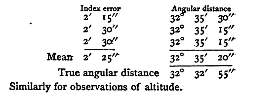
(1) Test the accuracy of the various adjustments of the sextant. Enter results thus:
|
||
| Home Mirrors and Lenses The Sextant |
|
|

Last Update: 2011-03-27