| Practical Physics is a free textbook on basic laboratory physics. See the editorial for more information.... |

|
Home  Mirrors and Lenses Measurement of the Focal Length of a Convex Lens - Third Method Mirrors and Lenses Measurement of the Focal Length of a Convex Lens - Third Method |
||||||


|
  |
|||||
Measurement of the Focal Length of a Convex Lens - Third Method
The methods already described for finding the focal lengths of lenses involve the measurement of distances from the lens surface, and consequently a certain amount of error is caused by neglecting the thickness of the glass of which the lens is composed. This becomes very important, in the case of short-focus lenses and of lens combinations. The following method avoids the difficulty by rendering the measurement from the lens surfaces unnecessary.
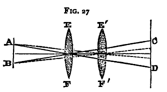
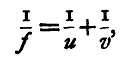
We know that for a convex lens, if u, v are the distances respectively of the image and object from the principal points(1) of the lens E F (fig. 27), and f its focal length; then
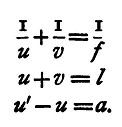
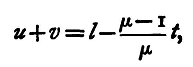
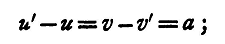
u and v being on opposite sides of the lens. Now, if we have two screens AB, CD a distance l apart, and we place the lens EF, so that the two screens are in conjugate positions with regard to it, then u+v = l, provided we neglect the distance between the two principal points. In strictness, u+v is not equal to l, as the distances u and v are not measured from the same point, but from the two principal points respectively, and these are separated by a distance which is a fraction of the thickness of the lens. Thus, if t be the thickness of the lens, it may be shown that the distance between the principal points is (μ-1)/μ*t, if we neglect terms involving t2; the value of this for glass is about 1/3t. The image of a cross-wire or a piece of wire-grating at the one screen AB will be formed at the other, CD. Now we can find also another position of the lens, E'F', between the screens, such that the image of the cross-wire or grating is again focussed on the second screen. This will evidently be the case when the lens is put so that the values of u and v are interchanged. Let u' and v' be the values which u and v assume for this new position of the lens, and let the distance u'-u or v-v1 through which the lens has been moved be a. Then we have
But
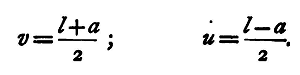
Hence
Substituting
so that the focal length may be determined by measuring the distance between the screens (which must be greater than four times the focal length), and the distance through which the lens lias to be moved in order to transfer it from one position in which it forms an image of the first screen on the second, to the other similar position. This latter measurement should be made three or four times and the mean taken. For screens, in this case, we may use small pieces of wire gauze mounted in the circular apertures of two of the stands of the optical bench, or we may fix two pins with their points at the centres of these apertures.
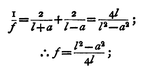
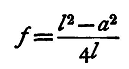
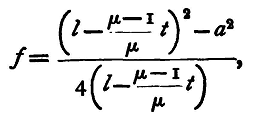
A lamp should be put behind one of the gauzes to increase the illumination, and care taken that the brightest part of the flame, the object, the centre of the lens, and the screen are in the same straight line. A special case of the foregoing is sometimes used for determining the focal length of a lens. From the formula
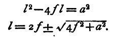
we see that if a=o, i.e. if the two positions of the lens coincide, then f = l/4, or one quarter of the distance between the screens. When this is the case the quantity l is at its minimum value; for solving the equation for l we get
The quantity l being the distance between the screens is essentially positive, so that the root with the negative sign gives no applicable result, hence the smallest value admissible is l = 2f + sqrt(4f2), which occurs when a = o, i.e. l = 4f. In this case u = v, or the image and object are at equal distances from the centre of the lens, and therefore the image is the same size as the object. This last property may be used to determine the focal length, by using as object a scale engraved on glass and as screen another such scale; adjust the lens and receiving scale so that for a particular coloured light the divisions of the image exactly correspond with the divisions of the scale on which it is received. Measure the distance of the screens apart, and divide by four, and we get the focal length of the lens. A magnifying glass should be used t.o observe the image, and the observation, as usual, repeated several times. We know that the focal length of a lens depends on the refractive index of the material of which it is composed, and that this is different for the different rays of the spectrum, so that we should expect to get different values for the focal length by illuminating the object with differently coloured rays. The methods just described for finding the focal length enable us to do this by placing between the lamp and the object plates of variously coloured glass, red, green, or blue, for example. The position of the receiving screen and consequent value of the focal length will differ in the three cases. Observations with the blue glass will present, perhaps, the greatest difficulty, for most blue glasses let through some red light as well, so that two images are formed a little way apart, one for the blue and the other for the red light. If, then, we 'are using the wire grating as object, the spaces, when focussed for blue light, will appear i>lue in the image and the wires red, while if we use the same glass in finding the focal length for the red light, we must focus so that the wires look blue and the spaces red. It is quite easy to adapt the method of this section for finding accurately the focal length of the lens, taking into account the thickness, as follows: Since u and v are measured from the principal points, and the distance between these is very nearly (μ-1)/μ*t, we have
or
and
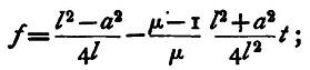
whence the expression for the focal length becomes
and this reduces to
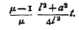
we have, therefore, to correct our first approximate value by subtracting the quantity
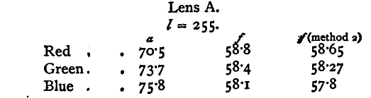
Experiment. - Determine the focal length of the given lens for red, green, and blue light, and verify your results by the modified method. Enter results thus:
|
||||||
| Home Mirrors and Lenses Measurement of the Focal Length of a Convex Lens - Third Method |
|
|||||


Last Update: 2011-03-27