| Practical Physics is a free textbook on basic laboratory physics. See the editorial for more information.... |

|
Home  Electricity Wheatstone's Bridge Electricity Wheatstone's Bridge |
|


|
  |
Wheatstone's Bridge
The method of comparing electrical resistances which has been already described depends on the measurement of the deflexion produced in a galvanometer, and we make the assumptions that the E.M.F. of the battery remains constant during the experiment, and that the relation between the current flowing through the galvanometer and the deflexion it produces is known. The disadvantages which thus arise are avoided in the Wheatstone bridge method, the principles of which we proceed to describe.
It follows from Ohm's law (p. 420) that, if a steady current be flowing through a conductor, then the electromotive force between any two points of the conductor is proportional to the resistance between those points. We can express this graphically thus. Let the straight line A B (fig. 63) represent the resistance between the two points A and B of a conductor, and let the line AD, drawn at right angles to AB, represent the electromotive force or difference of potential between A and B. Join DB, and let M be a point on the line AB, such that AM may represent the resistance between A and another point of the conductor. Draw ML at right angles to AB to meet BD in L, then LM represents the E.M.F. between M and B. For if C represent the current flowing through the conductor, then, by Ohm's law,
and since ML is parallel to DA,
But since MB represents the resistance and C the current between two points M and B, it follows from Ohm's law that LM represents the E.M.F. between those points. Now let A'B' represent the resistance between two points on another conductor, between which the E.M.F. is the same as that between A and B, and let A'D' represent this E.M.F.; then
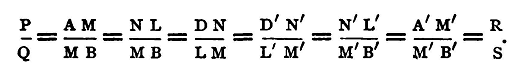
Join D'B', and in it take L'M', such that L'M' shall be equal to LM. Then M' will represent a point on the second conductor, such that the difference of potential between it and B' is equal to the difference of potential between M and B. Thus if B, B' be at the same potential, A, A' and M, M' respectively are at the same potentials. Hence, if MM' be joined through a galvanometer G, no current will flow through the galvanometer, and no deflexion, therefore, will be observed. We can now express the condition for this in terms of the four resistances AM, MB, A'M', M'B', Let these resistances respectively be denoted by P, Q, R, and S. Draw LN, L'N' parallel to AB and A'B'. Then clearly DN = D'N', and we have
Thus the condition required is
If, then, we have four conductors, AM, MB, A'M', M'B', and we connect together B and B', and so keep them at the same potential, and also connect A and A', thus keeping them at any other common potential then, provided the above condition holds, we may connect M and M' through a galvanometer without producing a deflexion; and conversely if, when MM' are thus connected, no deflexion be observed, we know that the above condition holds. Hence, if P and Q be any two known resistances, R any unknown resistance, and S an adjustable known resistance, and we vary S, the other connections being made as described, until no deflexion is observed in the galvanometer, R can be found, for we then have
and P, Q, S are known. In practice, to secure that B and B' should be at the same potential, they are connected together, and to one pole of a battery, A and A' being connected through a key, to the other pole.
Fig. 64 shows a diagram of the connections. AC, CB correspond to the two conductors AM, MB of fig. 63, while AD, DB correspond to A'M', M'B'. A key K' is placed in the galvanometer circuit and a second key K in the battery circuit. On making contact with the key K a difference of potential is established between A and B, and a current flows through the two conductors ACB and ADB. If on making contact with K' no deflexion is observed in the galvanometer, it follows that C and D are at the same potential, and therefore that
In practice P, Q, and S are resistance coils included in the same box, which is arranged as in fig. 65 for the purposes of the experiment, and is generally known as a Wheatstone-bridge box, or sometimes as a Post-Office box.
The resistances P and Q, which are frequently spoken of as the arms of the bridge, are taken, each from a group of three coils of 10, 100, and 1000 units. Thus, by taking the proper plugs out we may give to the ratio P/Q any of the values 100, 10, 1, 0.1, or 0.01. The resistance s is made up of 16 coils from 1 to 5000 ohms in resistance, and by taking the proper plugs out it may have any integral value between 1 and 10000 units. Thus the value of R may be determined to three figures if it lie between 1 and 10, or to four figures if it be between 10 and 1000000, provided, that is, the galvanometer be sufficiently sensitive. At A, B, C, and D are binding screws, those at A and D being double. By means of these the electrodes of the battery, galvanometer, and conductor whose resistance is required, are connected with the box. In some boxes the two keys, K and K', are permanently connected with the points A and C, being fixed on to the insulating material of the cover. The arrangement is then technically known as a Post-Office box. The galvanometer to be employed should be a sensitive reflecting instrument; the method of adjusting this has been already described (p. 404), while for a battery, one or two Leclanché or sawdust Daniell cells are generally the most convenient. The number of cells to be used depends, however, on the magnitude of the resistance to be determined and the sensitiveness of the galvanometer. The key K is inserted in the battery circuit in order that the battery may be thrown out, except when required for the measurement. The continual passage of a current through the coils of the box heats them, and if the current be strong enough may do damage. It will be noticed that at each of the points A, B, C, D, three conductors meet, and that including the galvanometer and battery there are six conductors in all, joining the four points A, B, C, D. When the resistances are such that the current in the conductor joining two of the points is independent of the E.M.F. in the conductor joining the other two, then those two conductors are said to be conjugate. In the Wheatstone's bridge method of measuring resistances the battery and galvanometer circuits are made to be conjugate; the current through the galvanometer is independent of the E.M.F. of the battery. If the equation P/Q = R/S holds, the galvanometer is not deflected whatever be the E.M.F. of the battery; there is no need, therefore, to use a constant battery. Moreover, since we only require to determine when no current flows through the galvanometer circuit, and not to measure a steady current, a sensitive galvanoscope is all that is necessary; we do not need to know the relation between the current and the deflexion produced by it
Fig. 66 is another diagram of the connections, which shows more clearly the conjugate relation. The conductors AB and CD are conjugate if the equation P/Q = R/S holds. It follows from this that we may interchange the galvanometer and battery without affecting the working of the method. The galvanometer may be placed between A and B, and the battery between C and D. The sensitiveness of the measurements will, however, depend on the relative positions of the two, and the following rule is given by Maxwell, 'Electricity and Magnetism,' vol. i. §348, to determine which of the two arrangements to adopt. Of the two resistances, that of the battery and that of the galvanometer, connect the greater resistance, so as to join the two greater to the two less of the other four. As we shall see directly, it will generally happen when making the final measurements, that Q and S are greater than P and R; thus, referring to fig. 65, the connections are there arranged to suit the case in which the resistance of the battery is greater than that of the galvanometer.
|
|
| Home Electricity Wheatstone's Bridge |
|


Last Update: 2011-03-19