| Practical Physics is a free textbook on basic laboratory physics. See the editorial for more information.... |

|
Home  Electricity Measurement of a Galvanometer Resistance - Thomson's Method Electricity Measurement of a Galvanometer Resistance - Thomson's Method |
||


|
  |
|
Measurement of a Galvanometer Resistance - Thomson's Method
It has been shown that if, in the Wheatstone's bridge arrangement, two of the conductors, as AB, CD (fig. 66, p. 442), are conjugate, then the current through the one due to an E.M.F. in the other is zero. It follows from this that the current through the other conductors is independent of the resistance in CD, and is the same whether CD be connected by a conductor or be insulated; for the condition that the two should be conjugate is that C and D should be at the same potential, and if this condition be satisfied there will never be any tendency for a current to flow along CD; the currents in the rest of the circuit will, therefore, not depend on CD.
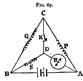
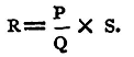
Suppose, now, a galvanometer is placed in the branch DA, and a key in CD (fig. 67), there will be a deflexion produced in the galvanometer. Adjust the resistance S until the galvanometer deflexion is unaltered by making or breaking contact in the branch CD. When this is the case it follows that AB and CD are conjugate, and, therefore, that
But R is the resistance of the galvanometer, which is thus measured by a null method without the use of a second galvanometer.
The battery used should be one of fairly constant E.M.F., for, if not, the current through the galvanometer will vary, and it will be difficult to make the necessary observations. The method of proceeding is the same as that employed in the last section; the arms p and Q are first made equal, and two values found, differing by one ohm, between which S lies. The ratio P/Q is then made 0.1, and the first decimal place in the value of R obtained, and so on. Experiment. - Determine, by Thomson's method, the resistance of the given galvanometer. Enter result thus: Galvanometer No. 6 Resistance 66.3 ohms.
|
||
| Home Electricity Measurement of a Galvanometer Resistance - Thomson's Method |
|
|

Last Update: 2011-03-27