| Electrical Engineering is a free introductory textbook to the basics of electrical engineering. See the editorial for more information.... |
|
Home  Circuits With Resistance, Inductance, and Capacitance Circuits With Resistance and Inductive Reactance Circuits With Resistance, Inductance, and Capacitance Circuits With Resistance and Inductive Reactance |
|||||||||||


|
  |
||||||||||
|
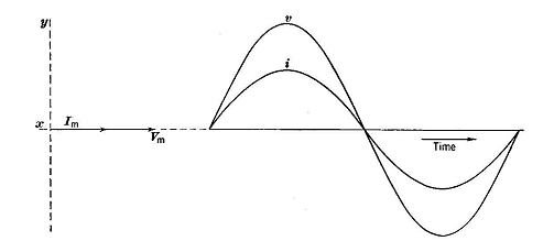
Circuits With Resistance and Inductive ReactanceAuthor: E.E. Kimberly In a circuit with resistance only, the current rises and falls in unison with the impressed voltage, according to Ohm's Law, as indicated in Fig. 5-4. There is no time-phase displacement between them.
If a circuit like that of Fig. 5-6 has induced in it an appreciable emf because of inductance, the impressed voltage V must be large enough to provide for the resistance voltage drop and also for the reactive voltage drop. The resistive voltage drop and the reactive voltage drop cannot be added algebraically because there is a time-phase displacement between them. Hence, they must be added vectorially.
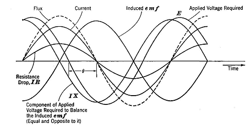
The resistive voltage drop IR through the circuit is that component of the applied voltage required to force the current through the resistance of the circuit. The reactive voltage drop IX through the circuit is that component of the applied voltage required to balance the opposing counter-voltage generated by the change in flux linkages. The magnetic field in a coil is in time phase with the coil current which produces it. The induced emf caused by the sinusoidal change in magnitude of flux is greatest when the flux is zero because the magnitude of a sinusoidal function is changing most rapidly when passing through zero value. Hence, the induced emf is greatest when the magnetic field and its parent current are passing through their zero values and is in such a sense as to oppose the change of current. But the resistance drop is greatest when the current is at its maximum. The resistive drop and the induced emf have a time-phase displacement of 90°, as indicated in Fig. 5-5.
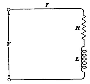
The applied voltage is the vector sum of the IR drop and the IX drop, and is in phase with no other variable. The current lags behind the applied voltage by the angle θ because of the inductance in the circuit. For convenience, a circuit with resistance and inductive reactance, such as a coil of wire, may be shown schematically with the resistance and reactance portions separated as in Fig. 5-6. If it were possible actually to separate R and L in a circuit, it would be possible to measure IR across R and IX across L with a voltmeter.
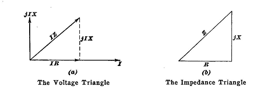
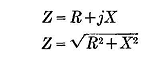
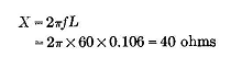
In Fig. 5-5, the voltage drop IX leads the voltage drop IR by 90°. The vector sum IR+jIX is called the impedance drop of the circuit and is symbolized by IZ. The relation of IR, IX, and IZ is shown in Fig. 5-7 (a). The impedance drop IZ of a circuit is always equal to the applied voltage E. Thus, V=IZ (5-5) Inasmuch as in a series circuit the current is common to all parts, it is convenient to use the current vector as a reference and to draw it hori zontally. If all sides of Fig. 5-7 (a) be divided by I, the result is the impedance triangle of Fig. 5-7 (b). The impedance Z of the circuit is, therefore, (5-6) or Example 5-3. - A pure resistance R = 50 ohms is connected in series with a pure inductance L = 0.106 henry to a 220-volt line whose frequency is 60 cycles per second. Find the current and the angle θ by which it lags the applied voltage. Solution. - In order to find the impedance, it is necessary first to compute the reactance, which is
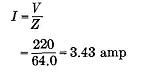
As shown in Fig. 5-8, the impedance is Since V = IZ, the
Also, the angle by which the current lags the voltage is Therefore,
The angle θ, as calculated in Example 5-3, is actually the angle between the resistance line and the impedance line. But the impedance drop is the applied voltage and the current is always in phase with the resistance drop. Therefore, θ is the angle by which the current lags the applied voltage. The angle θ is called the characteristic angle of the circuit. Inasmuch as a vector diagram is always associated with some circuit, a schematic diagram of the circuit should always be used with appropriate references clearly marked unless the circuit is so simple that lack of a circuit diagram will not lead to confusion.
|
|||||||||||
| Home Circuits With Resistance, Inductance, and Capacitance Circuits With Resistance and Inductive Reactance |
|
||||||||||