| Electrical Engineering is a free introductory textbook to the basics of electrical engineering. See the editorial for more information.... |
|
Home  Circuits With Resistance, Inductance, and Capacitance Parallel Circuits with Resistance and Inductance Circuits With Resistance, Inductance, and Capacitance Parallel Circuits with Resistance and Inductance |
|||||


|
  |
||||
|
Parallel Circuits With Resistance and InductanceAuthor: E.E. Kimberly When circuit parts with resistance and inductance are connected in parallel to a common source of alternating voltage, the current in each parallel part will have the same magnitude and phase relation to the applied voltage as if each circuit existed alone. The total current drawn from the source will be the vector sum of the currents in the parts that are in parallel. Inasmuch as the applied voltage is common to all the circuit branches, it is customary to lay out the voltage vector horizontally and to refer all current vectors to it.
Example 5-5. - In Fig. 5-11 are represented three branches of a circuit with resistances and 60-cycle reactances which are connected in parallel to a 220-volt, 60-cycle line. The resistances and reactances have the following magnitudes:
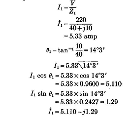
Find the current in each branch. Find the total current taken from the line and its phase displacement from the applied voltage. Solution. - In branch 1,
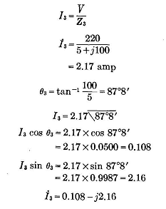
In branch 3t
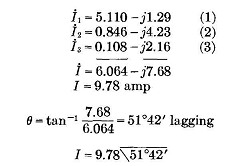
The current I taken from the line may be found by combining the components of the currents in the branches, as follows:
The vector diagram is shown in Fig. 5-12.
|
|||||
| Home Circuits With Resistance, Inductance, and Capacitance Parallel Circuits with Resistance and Inductance |
|
||||
 (1)
(1) 
 (2)
(2)  (3)
(3)