| Electrical Engineering is a free introductory textbook to the basics of electrical engineering. See the editorial for more information.... |
|
Home  Polyphase Circuits Three-Phase Circuits Polyphase Circuits Three-Phase Circuits |
|||||


|
  |
||||
|
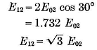
Three-Phase CircuitsAuthor: E.E. Kimberly Fig. 9-1 (a) is a three-dimensioned representation of a magnetic field in which there are three revolving conductors displaced 120 degrees from one another on their common circular path.1 The voltages generated in them will then be displaced in time by 120 degrees, as shown in Fig. 9-1 (b) by the sinusoids e01, e02, and e03 and their corresponding vectors. The conductors will be said to have a positive sense from the back, or zero, end toward the nearer end, as indicated by the sequence of the numbers in the subscripts identifying the vectors which represent the voltages generated in them. It is common practice to connect the conductors or phases inside the machine, as at 0, so that the terminals 1, 2, and 3 only are necessary to connect the machine to its load. The generator is then said to be Y-connected or wye-connected. A voltmeter connected to the terminals 1 and 2 in Fig. 9-1 (a) would be affected by the voltages E01 and E02. However, if the circuit be traced through the two conductors from terminal 1 to terminal 2, the course would be in a negative sense through conductor 1 and in a positive sense through conductor 2. Therefore, the voltage appearing between terminals 1 and 2 will be the vector difference of E01 and E02, and not their vector sum. It is not important whether this vector difference be taken as E01-E02 or E02-E01. If, however, the voltage between terminals 1 and 2 is to be called E12, and the double subscript is to be consistent in denoting the vector direction, it is necessary that E12 = E02 - E01. Likewise, E23 = E03 - E02 and E31 = E01 - E03. The voltages E01, E02, and E03 are called the phase voltages; and E12, E23, and E31 are called the line-to-line voltages or simply the line voltages. The voltage at which a generator is rated is always the line voltage, unless otherwise stated. By the trigonometry of Fig. 9-1 (b),
Since E01 = E02 (in magnitude), or
 times the phase voltage or line-to-neutral voltage. times the phase voltage or line-to-neutral voltage.
|
|||||
| Home Polyphase Circuits Three-Phase Circuits |
|
||||