| Electrical Engineering is a free introductory textbook to the basics of electrical engineering. See the editorial for more information.... |
|
Home  Polyphase Circuits The Balanced Three-Phase Wye-Connected Load Polyphase Circuits The Balanced Three-Phase Wye-Connected Load |
|||


|
  |
||
|
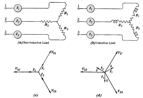
The Balanced Three-Phase Wye-Connected LoadAuthor: E.E. Kimberly If three identical resistances R1 R2, and R3 or three identical impedances Z1, Z2, and Z3 are connected in wye, as in Fig. 9-2 (a) or 9-2 (b), and are then connected to a source of three-phase voltages, three equal currents will flow in the branches of the load circuit thus constructed. Voltage drops V01 = I1Z1, V02 = I2Z2, and V03 = I3Z3 will appear across the impedances. If the impedances are purely resistive, as in (a), the currents will be in phase with the voltage drops across the respective impedances, as in (c). If the impedances contain both resistances and inductances, as in (b), the currents will lag the respective voltage drops by the angle θ, as in (d), where θ is the characteristic impedance angle as has previously been explained for the usual single-phase circuit. The phase currents in the impedances are, of course, the line currents I1, I2, and I3.
|
|||
| Home Polyphase Circuits The Balanced Three-Phase Wye-Connected Load |
|
||