| Electrical Engineering is a free introductory textbook to the basics of electrical engineering. See the editorial for more information.... |
|
Home  The Direct-Current Machine The Compound Generator The Direct-Current Machine The Compound Generator |
|||||||


|
  |
||||||
|
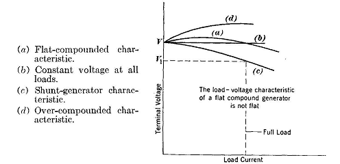
The Compound GeneratorAuthor: E.E. Kimberly Curve (c) of Fig. 10-16 corresponds to the condition of fixed field-circuit resistance in a shunt generator adjusted to give rated voltage V1 at rated load. If the no-load voltage had been set at V, as in Fig. 10-17, the full-load voltage for operation indicated by curve (c) would have been F1 which is much too low. The voltage may be kept constant at all loads, as indicated by curve (b), by adjustments of the field rheostat. The tendency for the voltage to fall when the load current is increased is then just balanced by the increased excitation accomplished by adjustment of the rheostat.
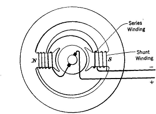
A performance somewhat similar to that indicated by curve (6) may be obtained automatically by causing the load current to flow through a few turns of heavy wire on each field pole. The series-field exciting ampere-turns thus added to the shunt-field exciting ampere-turns increase the total ampere-turns in direct proportion to the load current. If there were no magnetic leakage and no armature reaction, and the saturation curve of iron were a straight line, the curve (b) could be almost exactly realized. However, the actual performance will be more like that indicated by curve (a). Such a generator with both shunt-field and series-field windings is called a compound generator. A wiring diagram for a compound generator is shown in Fig. 10-18.
When the series-field ampere-turns aid the shunt-field ampere-turns, as just described, the machine is called a cumulative compound generator. Such generators are used to supply most d-c distribution systems. They may be over-compounded to compensate for voltage lost in IR drop in feeders. If the series-field ampere-turns tend to produce flux in a direction opposite to that of the flux produced by the shunt-field ampere-turns, the machine is called a differential compound generator.
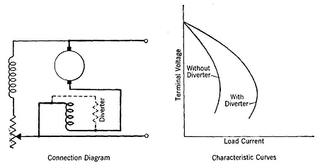
Such generators have very few practical applications, but are ideally suited to supplying power to electrically powered excavators, inasmuch as the drooping voltage characteristic prevents stalling of the driving engine when the excavating bucket is accidentally stalled. A cumulative compound generator whose series-field ampere-turns at full load are just sufficient to produce the terminal voltage that the generator has at no load, as indicated by curve (a) of Fig. 10-17, is said to be flat-compounded. It should be noted that in a flat-compounded generator the terminal voltage is not constant between no load and full load, as the name flat implies. If the full-load voltage is greater than the no-load voltage, the generator is said to be over-compounded. The degree of compounding of a finished generator may be adjusted by placing a suitable low-resistance, high-current-capacity resistor in parallel with the series field and thus by-passing more or less of the load current. Such by-pass resistors are called diverters. Diverters are usually made of nickel-silver strip. The arrangement of a diverter on a differential compound generator and the effect of the diverter on the characteristic curve are shown in Fig. 10-19.
|
|||||||
| Home The Direct-Current Machine The Compound Generator |
|
||||||