| Electrical Engineering is a free introductory textbook to the basics of electrical engineering. See the editorial for more information.... |
|
Home  The D-C Machine as a Motor Lenz's Law The D-C Machine as a Motor Lenz's Law |
|||
| See also: Application of Faraday's Law and Lenz's Law | |||


|
  |
||
|
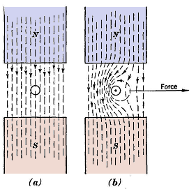
Lenz's LawAuthor: E.E. Kimberly In Fig. 11-1 (a) is shown an endwise view of a conductor immersed in a magnetic field, but carrying no current. No force is exerted on that conductor by the field. In (b) is shown the effect of passing an electric current through the conductor. The magnetic rule of thumb stated on page 5 will be found useful in studying the action in Fig. 11-1 (b). With the current flowing toward the observer, the magnetic flux produced by it encircles the conductor in a counter-clockwise direction, thus strengthening the main field on the left of the conductor and weakening it on the right of the conductor. This distortion of the main field produces a force to the right on the conductor. By experiment, it has been found that the force on the conductor is directly proportional to the current in the conductor and to the strength of the main magnetic field.
It should be noted that, if the current flowing toward the observer as in Fig. 11-1 (b), and the conductor were forced to move to the left against the magnetic force on it, the voltage generated in it would, according to Faraday's Law, be in a direction toward the observer. Lena's Law summarizes the foregoing facts by stating that a current induced in a conductor always produces a force which opposes the action that induces the current. A current of 1 abampere, or 10 amperes, in a conductor located in a magnetic field with a strength of 1 gauss in a direction perpendicular to the conductor will cause each centimeter of length of that conductor to be acted upon by a force of 1 dyne. It therefore follows that, under the same conditions, 1 ampere will cause a force of iV dyne per centimeter of immersed length of conductor. Hence, the force on a conductor may be expressed in terms of the intensity of the field in which it is immersed and the conductor length normal to the flux lines. The relation is:
in which B = field intensity, in lines per square centimeter; I = current, in amperes; l = length of conductor normal to the field, in centimeters.
|
|||
| Home The D-C Machine as a Motor Lenz's Law |
|
||