| Electrical Engineering is a free introductory textbook to the basics of electrical engineering. See the editorial for more information.... |
|
Home  Electrical Instruments and Meters Watt-Hour Meters Electrical Instruments and Meters Watt-Hour Meters |
|||||||||


|
  |
||||||||
|
Watt-Hour MetersAuthor: E.E. Kimberly Watt-hour meters are essentially motors so designed that the speed is proportional to the power taken through them by the load. The motor is geared to a gear-train register, and hence the register reading is a product of power and time and indicates directly the work done in kilowatt-hours.
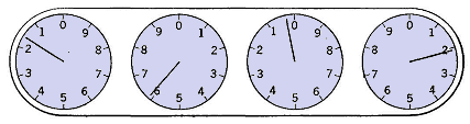
The dials of the register are read from left to right. The figure read on each dial is the one which the pointer points to or pointed to last. In Fig. 16-14 the reading is 1602 kw-hr.
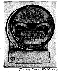
Direct-current watt-hour meters are of the commutator-motor type or of the mercury type. The single-phase watt-hour meter, an example of which is shown in Fig. 16-15, operates on the induction-motor principle.
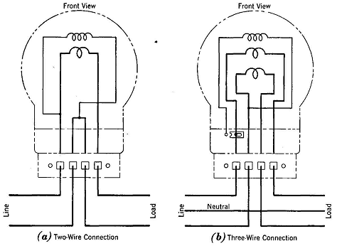
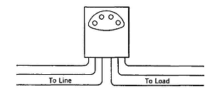
The speed of the disc armature is proportional to the power of the load. In Fig. 16-16 (a) is shown the proper method of connecting a two-wire single-phase meter, and in (b) is shown the proper method of connecting a three-wire meter for measuring power in a single-phase, three-wire circuit as supplied by the transformer of Fig. 17-7. The two-element polyphase watt-hour meter contains two motor elements driving the same register, and is connected in the same manner as a polyphase indicating wattmeter, as indicated in Fig. 16-17. However, the third wire is also connected to the meter in order that potential-coil connections may be made permanently when the meter is assembled.
Watt-hour meters for use on four-wire, three-phase circuits contain three motor elements and are connected essentially in the manner shown for the three meters in Fig. 9-12. A diagram of connections is usually furnished with each meter. When the load being metered by a two-element polyphase watt-hour meter is reasonably steady, it is sometimes convenient to be able to determine the power, the current, and the power factor of the load without the use of additional meters if the watt-hour meter is not sealed. It must first be assumed that the voltage of the line is at its rated value. The potential coils of the meter are provided with small links or other means for disconnecting the coils for calibration purposes. To carry out the calibration, disconnect one element and count the revolutions of the disc for a minute; call this number S1. Reconnect the element, and repeat the counting procedure with the other element disconnected; call this number S2. If it is assumed that S1 is larger
and
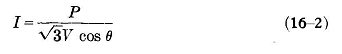
where Kh = disc constant = number of watt-hours per revolution. Also,
|
|||||||||
| Home Electrical Instruments and Meters Watt-Hour Meters |
|
||||||||