| Electrical Engineering is a free introductory textbook to the basics of electrical engineering. See the editorial for more information.... |
|
Home  Transformers The Equivalent Circuit of a Transformer Transformers The Equivalent Circuit of a Transformer |
|||


|
  |
||
|
The Equivalent Circuit of a TransformerAuthor: E.E. Kimberly The leakage impedances of a transformer cause a voltage loss between line and load exactly the same as if they were not in the transformer but in the lines to or from the transformer. The exciting current Ie remains substantially the same for all loadings. If a circuit be made up of two branches in parallel, as in Fig. 17-2 (a), the voltage at the load and the current in the supply line will be the same as actually would occur if a transformer with a 1:1 ratio and the same values of X and R were used. Such a circuit is called the equivalent circuit of the transformer because its effect between the supply line and the load would be the same. If the turns ratio is not 1:1, a modification in the circuit elements must be made to suit the turns ratio. For any definite secondary load, the primary current will be the same regardless of the turns ratio because N2I2 merely produces a magnetomotive force mmF2 which must be balanced by the force mmF1 at the available supply voltage. If the transformer had a turns ratio of 4:1 and both windings had the same size of wire, their resistances would be in the same ratio and R1 would equal 4R2. However, if the volt-ampere input and the volt-ampere output are to be equal, then I2 = 4I1 and the current-carrying capacity of the secondary coil conductor must be four times that of the primary coil conductor. As a result, the secondary conductor must have four times the cross-sectional area and, therefore, one-fourth of the resistance per turn. Hence,
Since
Regardless of the value of the ratio
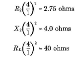
Example 17-1. - A 5-kv-a transformer with a 4:1 turns ratio is to be used to supply 110 volts to a resistive load which draws full rated current from the transformer. The transformer constants are: R1 = 2.75 ohms, R2 = 0.172 ohm, X1 =4.0 ohms, and X2 = 0.25 ohm; and the load resistance is RL = 2.5 ohms. Calculate the necessary primary applied voltage.
Solution. - The rated currents are: Primary........ .5000 /440 = 11.38 amp Secondary....... 5000 / 110 = 45.45 amp Also,
Then,
|
|||
| Home Transformers The Equivalent Circuit of a Transformer |
|
||