| Electrical Engineering is a free introductory textbook to the basics of electrical engineering. See the editorial for more information.... |
|
Home  Transformers Additive and Subtractive Polarity Transformers Additive and Subtractive Polarity |
|||


|
  |
||
|
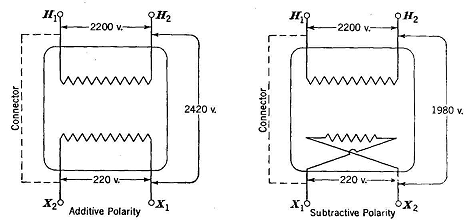
Additive and Subtractive PolarityAuthor: E.E. Kimberly When transformers are to be connected in parallel or in groups for three-phase service, identification of their terminal polarities is imperative. A transformer with additive polarity is connected internally so that, if its primary coil be excited and one primary terminal be connected to the secondary terminal nearest it, a voltmeter connected between the other two terminals of the two windings will indicate the sum of the primary and secondary voltages. If, when the transformer is so connected and excited, the voltmeter indicates the difference between the primary and secondary voltages, the transformer is said to be of subtractive polarity. Fig, 17-6 indicates the two types of internal connections. A standard plan of marking the terminals of power transformers has been adopted by the National Electrical Manufacturers Association so that interconnection of units may readily be made without polarity tests. When an observer faces the high-voltage side of the transformer, the extreme right high-voltage lead will be H1 Other high-voltage leads reading right to left will be H2, H3, H4, etc. Facing the low-voltage side of the transformer, the observer will see the low-voltage leads marked X1, X2, X3 etc., reading from either right or left. If terminal X1 is diagonally across the transformer from H1, the transformer is of additive polarity. When H1 and X1 are adjacent, the transformer is of subtractive polarity.
|
|||
| Home Transformers Additive and Subtractive Polarity |
|
||