| Electrical Engineering is a free introductory textbook to the basics of electrical engineering. See the editorial for more information.... |
|
Home  The Polyphase Induction Motor The Polyphase Induction Motor The Polyphase Induction Motor The Polyphase Induction Motor |
|||


|
  |
||
|
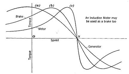
The Polyphase Induction MotorAuthor: E.E. Kimberly The speed-torque curves of Fig. 18-9 are only motor characteristics of much more extensive general curves such as those shown in Fig. 18-19. If a rotor with characteristic (a), (b), or (c) is driven above its synchronous speed S by external means in a stator normally excited, its torque becomes negative and the motor becomes an induction generator delivering electrical power back into the system to which it is connected. The power factor and the power output of an induction generator are determined by its design and the speed at which it is driven, and are independent of the character of the load, An induction generator cannot supply magnetizing current to inductive reactive loads and' must be operated in parallel with a synchronous generator which will supply its magnetizing current and also establish and control its frequency.
Furthermore, if an induction motor (while normally excited) be driven in a direction opposite to that of its torque, as in the region to the left of point 0 in Fig. 18-19, it will convert both mechanical energy and electrical energy into heat and will act as a brake. Thus, an induction motor will act as a brake if driven backward or if driven above its synchronous speed while connected to its power line. Such means are sometimes used to control the rate of stopping a connected device such as a small hoist. A multi-speed motor running at its high speed will, when changed to a reduced synchronous speed, decelerate to that speed very quickly because of regenerative braking at all speeds higher than the reduced synchronous speed. The low speed is convenient in "inching" a load, as when adjusting a machine tool or when leveling an elevator car that is to be stopped at a floor.
|
|||
| Home The Polyphase Induction Motor The Polyphase Induction Motor |
|
||