| Electrical Engineering is a free introductory textbook to the basics of electrical engineering. See the editorial for more information.... |
|
Home  Alternating-Current Generators Parallel Operation Alternating-Current Generators Parallel Operation |
|||||||


|
  |
||||||
|
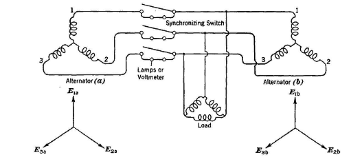
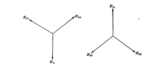
Parallel OperationAuthor: E.E. Kimberly The economic generation of alternating current frequently involves parallel operation of two or more alternators. Direct-current generators excited to the same terminal voltage may be connected in parallel merely by connecting together terminals of like polarity. However, before two or more alternators can safely be connected in parallel, their frequencies must be almost the same and their terminal voltages must be almost the same. Furthermore, the terminal voltages of the machines must be almost in phase. Fig. 20-8 shows a circuit diagram of two three-phase alternators arranged to be operated in parallel, and shows also the ideal vector relationship desirable at the instant of closing the synchronizing switch. If the speed of the incoming alternator (a) is slightly greater than that of alternator (b), there will be alternate instants when the respective phase voltages of the two machines will be in phase, as in Fig. 20-8, and 180° out of phase, as in Fig. 20-9.
When the respective phase voltages of the two generators are exactly out of phase, the lamps of Fig. 20-8 will receive the combined voltage of both alternators in series and will be fully lighted. If the synchronizing switch were closed at that instant, the combined voltages of the alternators would be applied to their combined impedances only, and there would result a tremendous short-circuit current which would possibly damage the alternators.
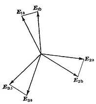
If, however, the switch be closed when the voltages of the two alternators are in phase, as in Fig. 20-8, the resultant voltage across the lamps will be zero, the lamps will be dark, and no circulating current will flow. This method is called "dark-lamp" synchronization. Fig. 20-10 shows the vectors of Fig. 20-8 superposed at an instant when alternator (a)has drifted somewhat past the proper synchronizing point and resultant voltages E1aE1b, E2aE2b ,and E3aE3b have appeared across the synchronizing lamps. The shock to the alternators resulting from careless timing of the synchronizing switch is proportional to these resultant voltages.
Significance of Phase Sequence.If the phase sequences of the alternators in Fig. 20-8, as seen at the synchronizing switch, are the same, all the lamps will brighten and darken in unison as synchronism is approached. If they do not so brighten and darken in unison, but the brilliance seems to "rotate," then the phase sequences are not the same and the synchronizing switch must not be closed. The phase sequence may be corrected by reversing only two leads on either side of the synchronizing switch.
|
|||||||
| Home Alternating-Current Generators Parallel Operation |
|
||||||