| Electrical Engineering is a free introductory textbook to the basics of electrical engineering. See the editorial for more information.... |
|
Home  Illumination Light Control Illumination Light Control |
|||||||||||||||||||||||||||||||||||||||||||||||||||||||||||||||||||||||||||||||||||||||||||||||||||||||||||||||||||||||||||||||||||||||||||||||||||||||||||||||||||||||||||||||||||||||||||||||||||||||||||||||||||||||||||||||||||||||||||||||||||||||||||||||||||||||||||||||||||||||||||||||||||||||||||||||||||||||||||||||||||||||||||||||||||||||||||||||||||||||||||||||||||||||


|
  |
||||||||||||||||||||||||||||||||||||||||||||||||||||||||||||||||||||||||||||||||||||||||||||||||||||||||||||||||||||||||||||||||||||||||||||||||||||||||||||||||||||||||||||||||||||||||||||||||||||||||||||||||||||||||||||||||||||||||||||||||||||||||||||||||||||||||||||||||||||||||||||||||||||||||||||||||||||||||||||||||||||||||||||||||||||||||||||||||||||||||||||||||||||||
|
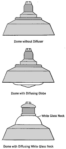
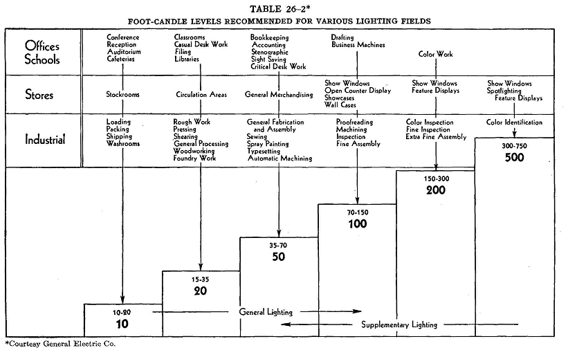
Light ControlAuthor: E.E. Kimberly The eye must be protected from light that comes directly from a high-intensity source. This is done by redirecting some or all of the light upon the surface to be illuminated, or by enclosing the lamp in translucent glassware. Redirection is accomplished by reflectors, which not only salvage the light directed in non-useful angles but also diffuse that light to produce a soft illumination. Such light control produces direct lighting with a maximum efficiency of use of the light flux. Direct-lighting units must be so arranged that the eye in the usual working positions will receive no glare, either directly from the lamp itself or from reflecting polished surfaces. Light that is directed upward and reflected from a light-colored ceiling produces a more pleasing effect than does direct lighting, because of more effective diffusion. This type of lighting is said to be indirect. Indirect lighting, while most pleasing of all, is also least effective in its use of light flux. Semi-indirect lighting is accomplished with a luminaire which directs most of its light toward the ceiling but permits some to pass directly into the room. Selection of Industrial Lighting Units. General overhead industrial lighting is usually accomplished by the use of incandescent lamps with the RLM (Reflector and Lamp Manufacturers') Standard Dome Reflectors shown in Fig. 26-7, or by multiple units-of fluorescent lamps. The selection and placing of incandescent units may be accomplished with the aid of Tables 26-1 and 26-2, as follows: Step 1. Determine the mounting height as the highest point above the floor at which the reflectors can be suspended without interference with belting, shafting, etc. Step 2. Refer to Table 26-1 and, with the mounting height of step 1, ascertain the proper spacing distance. If spacing so obtained does'not fit well in the building bays, a smaller spacing with a lower mounting height should be used. Step 3. Select from Table 26-2 the foot-candle illumination required by the class of work, and find the nearest corresponding value in Table 26-1 under the selected spacing distance. Step 4- Having found the proper foot-candle intensity, read, from the first column in Table 26-1 on the left, the lamp size required. Reflectors must be bought to fit the lamp size,
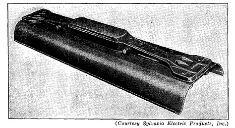
CPID 260 TWO-LAMP FIXTURE FOR 100-WATT LAMPS
The procedure just outlined does not allow for reflection from walls, and takes no account of the height of room in relation to its width.1 Table 26-1 is only for low-level general lighting. Selection and spacing of other types of units should be carried out according to the recommendations of the manufacturer. In some installations, building vibration is so severe as to reduce seriously the life of lamps. Special shock-absorbing hangers are recommended for such service.
Fig. 26-8 shows an industrial type of fluorescent-lamp fixture for two 100-watt lamps. Table 26-3 shows the proper spacing and mounting height to obtain any normally used intensity of lighting with such a fixture.
|
|||||||||||||||||||||||||||||||||||||||||||||||||||||||||||||||||||||||||||||||||||||||||||||||||||||||||||||||||||||||||||||||||||||||||||||||||||||||||||||||||||||||||||||||||||||||||||||||||||||||||||||||||||||||||||||||||||||||||||||||||||||||||||||||||||||||||||||||||||||||||||||||||||||||||||||||||||||||||||||||||||||||||||||||||||||||||||||||||||||||||||||||||||||||
| Home Illumination Light Control |
|
||||||||||||||||||||||||||||||||||||||||||||||||||||||||||||||||||||||||||||||||||||||||||||||||||||||||||||||||||||||||||||||||||||||||||||||||||||||||||||||||||||||||||||||||||||||||||||||||||||||||||||||||||||||||||||||||||||||||||||||||||||||||||||||||||||||||||||||||||||||||||||||||||||||||||||||||||||||||||||||||||||||||||||||||||||||||||||||||||||||||||||||||||||||