| Electrical Engineering is a free introductory textbook to the basics of electrical engineering. See the editorial for more information.... |
|
Home  Electronic Devices The Alternating-Current Equivalent Circuit Electronic Devices The Alternating-Current Equivalent Circuit |
|||


|
  |
||
|
The Alternating-Current Equivalent CircuitAuthor: E.E. Kimberly For the circuit of Fig. 27-13, the equation for plate current change is
Also,
Therefore,
By simplifying the equation, we obtain Since gmrp = μ,
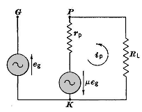
It follows, therefore, that a generator having a voltage μ Δee and connected in series with the anode would produce the same change Δtp in the plate current as Δeg in the grid circuit actually does. It is therefore feasible to replace the actual circuit with an equivalent circuit such as that shown in Fig. 27-14. The battery voltage Ebb is not shown because Δip is only the usable incremental part of the total plate current. If the simple equivalent circuit is to be used, it is necessary that the triode be operated on the linear portion of its characteristic. If eg is a sinusoid, then Equation (27-12) may be written as a vector equation as follows:
where
The alternating component of plate voltage is
The gain of the amplifier of Fig. 27-13 is then expressed as follows:
|
|||
| Home Electronic Devices The Alternating-Current Equivalent Circuit |
|
||