| Capacitors, Magnetic Circuits, and Transformers is a free introductory textbook on the physics of capacitors, coils, and transformers. See the editorial for more information.... |

|
Home  Energy Resistance and Capacitance Energy Resistance and Capacitance |
|||||||||||||||||||


|
  |
||||||||||||||||||
Resistance and Capacitance
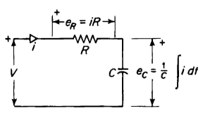
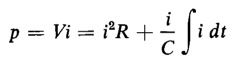
Figure 1-10 shows a circuit of capacitance in series with resistance. When a voltage is sustained across such a circuit the capacitance has energy that is stored electrostatically. The mathematical relationships in this kind of a circuit are quite similar to those in the mechanical system involving elasticity and friction. In Fig. 1-10 a constant voltage V is applied and
and
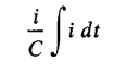
is the expression for power. The term i2R expresses the power that is converted into heat and the term
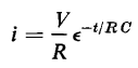
expresses the power that stores energy in the capacitance. The solution of Eq. 1-51 for the condition that when t = 0 there is no energy stored in the capacitance, yields
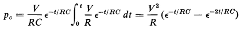
In Eq. 1-51 the power that stores energy in the capacitance is expressed by the term
If Eq. 1-52 is substituted in this term, the result is
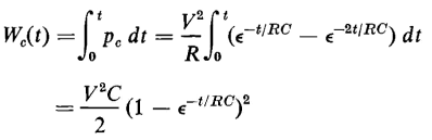
The energy stored in the capacitor at any time t after the constant voltage V is applied to the circuit is expressed by
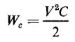
The energy in the capacitance approaches its final value as t approaches infinity. Hence, from Eq. 1-54
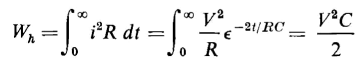
The expression for the energy converted into heat is from Eq. 1-52
Equations 1-55 and 1-56 show that the energy converted into heat in the R-C circuit with constant applied voltage is equal to the energy stored in the capacitor as time increases without limit. In the case of the spring under constant applied force, the total energy converted into heat is also equal to the energy stored in the spring as time increases without limit.
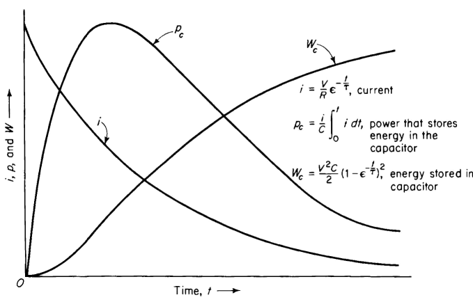
The variation with respect to time of current, power and, energy in the capacitor is shown graphically in Fig. 1-11. The same graph can be used to express the relationships for the massless spring. In that case the curve that shows the relationship between current and time in Fig. 1-11 would show the variation of the velocity of the force F in Fig. 1-9. Similarly the curve pc in Fig. 1-11 would indicate the power that stores energy in the spring as a function of time, whereas the curve wc would show the amount of energy stored in the spring as a function of time. The time constant for the R-C circuit is τ = RC sec. Similarly the time constant for the mechanical system with the massless spring is τ = RF/S sec.
|
|||||||||||||||||||
| Home Energy Resistance and Capacitance |
|
||||||||||||||||||


Last Update: 2011-01-11