| Capacitors, Magnetic Circuits, and Transformers is a free introductory textbook on the physics of capacitors, coils, and transformers. See the editorial for more information.... |

|
Home  Capacitance and Related Effects Energy Stored in a Dielectric Capacitance and Related Effects Energy Stored in a Dielectric |
|||||||||||||||||||||||


|
  |
||||||||||||||||||||||
Energy Stored in a Dielectric
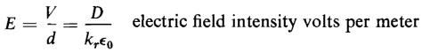
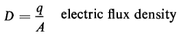
The amount of energy that can be stored in a dielectric is theoretically limited by the electric field intensity that the material can withstand. For example air under standard conditions of temperature and barometric pressure has a dielectric strength of approximately 3 million v per m. If the electric field intensity exceeds this value, air breaks down. Energy stored in dielectrics plays an important part in the operation of such devices as oscillators and in the characteristics of high-voltage transmission lines. Consider a section of area A in the parallel-plate capacitor of Fig. 2-13. The distance between plates, i.e., the thickness of dielectric, is d. The reason for selecting a section in this capacitor well away from the edges is to avoid the effects of fringing in this analysis. Hence, the electric flux density D is uniform throughout this section. Let A = plate area of the section Then
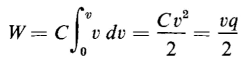
where q = charge in coulombs in the section of area A. The incremental energy in the capacitor is dW = v dq and dq = C dv where C = capacitance of the section in farads. Then
and
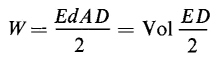
Equations 2-56, 2-57, and 2-58 yield
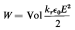
If E is the electric field intensity in any unit of length and D is the electric flux density in the same unit of area, then ED/2 is the energy per unit volume in those same dimensions. The quantity ED/2 is also known as the energy density of the electric field. Equation 2-59 can be rewritten as
or as
Equations 2-60 and 2-61 are valid only for configurations in which the electric field intensity is uniform. Such is the case for capacitors with plane parallel plates in which the area is so large, relative to the separation, that fringing is negligible. Capacitors with liquid-impregnated paper or solid-impregnated paper or dielectric, and generally those with mica as a dielectric, are assumed to have uniform electric field intensity. Figure 2-18(a) shows a section of paper and foil for a liquid-impregnated capacitor. Figure 2-18(b) shows an assembly of 10 paper-foil sections in which there are two sets of five sections in parallel. The two sets are in series. The plates in the capacitor sections in Fig. 2-18(a) and (b) are two long foils (usually aluminum), 0.00025 in. thick. The dielectric between foils is several layers of kraft paper ranging in thickness from 0.00020 in. to 0.001 in. Liquids commonly used for impregnating the paper are mineral oil with a relative dielectric constant kr = 2.2, chlorinated diphenyl with a kr of 4.9 and occasionally specially refined castor oil with a kr of 4.7. The impregnant increases the capacitance and the dielectric strength. Equation 2-60 shows that the amount of energy stored in a given volume of a certain dielectric is proportional to the square of the electric field intensity as long as the relative dielectric constant kr does not vary with electric field intensity. The variation of kr with electric field intensity is negligible for most dielectric materials in the normal operating range. We might thus have two parallel-plate capacitors of capacitances C1 and C2 rated at voltages V1 and V2 having thicknesses of identical dielectric material of d1 and d2
respectively. If both capacitors operate at the same value of electric field intensity of E v per m, then
Also, from Eq. 2-55, if the stored energy is to be the same in both capacitors, there is the relation that
from which we get
From Eqs. 2-33, 2-62 and 2-63 we get
The product of area A and thickness d gives the volume of the dielectric. Equation 2-64 simply bears out Eq. 2-60 and shows that in capacitors equal volumes of dielectric will store the same amount of energy at the same value of electric field intensity regardless of the relative values of the capacitance.
In the case of large capacitors, such as are used on electric power, transmission, and distribution systems, it is generally not practical from the standpoint of manufacturing costs to build capacitors with widely differing thicknesses of dielectric between the metal foils. Instead, the capacitors are made up of sections, as shown in Figs. 2-18(b) and 2-19, that are connected in series-parallel combinations to give the desired value of capacitance. There is also a practical lower limit to thickness of the dielectric. This means that below a certain value of operating voltage (about 460 v for capacitors used in distribution systems) the electric field intensity is reduced from values that can be used at the higher voltage ratings.
|
|||||||||||||||||||||||
| Home Capacitance and Related Effects Energy Stored in a Dielectric |
|
||||||||||||||||||||||


Last Update: 2011-08-01