| Capacitors, Magnetic Circuits, and Transformers is a free introductory textbook on the physics of capacitors, coils, and transformers. See the editorial for more information.... |
|
Home  Magnetic Circuits Magnetic Field About a Straight Wire Magnetic Circuits Magnetic Field About a Straight Wire |
|||||||||||||||||||||||||||||


|
  |
||||||||||||||||||||||||||||
Magnetic Field About a Straight Wire Carrying Current
An electric charge in motion constitutes an electric current. Then
where i = current in amperes Accordingly, an electric current is commonly described as a flow of electrons. Such a concept can be very misleading as it could easily lead to the erroneous conclusion that when the current in a conductor, as read by an ammeter, is zero all electron motion is arrested. This is far from the real condition. Actually, an enormous number of electrons swarm about in a conductor material with a random chaotic motion at velocities far greater than can be imparted to them by the application of an external voltage. The random current density or current crossing a unit surface in the conductor because of random electron velocities, found by taking into account only the electrons crossing in one direction and neglecting the equal numbers crossing in the other direction, is of the order of 1017 amp per sq m. An external voltage produces only a very minor modification of the random velocities, causing a drift in the direction of the electric field resulting from the applied voltage. This drift gives rise to a net current density of the order of 1.5 x 10⁶ amp per sq m for the values of electric field intensity normally encountered in metallic conductors such as are considered in the following. The magnetic field produced by a filament of current will be treated first and the results then applied to long straight cylindrical conductors such as wires.
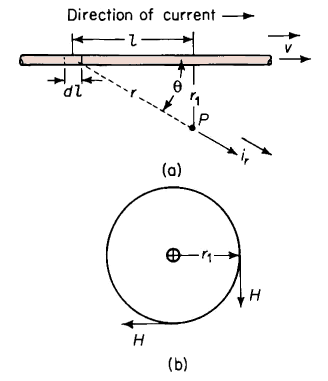
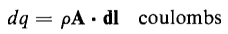
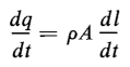
Figure 3-2 shows a straight filament carrying an electric current. Consider the point P, external to the wire, at which the magnetic field intensity produced by the current in the wire is to be determined. Then for a differential length of wire dl let ρ = net density of charge in coulombs per cubic meter drifting along the length of the wire The net electrical charge drifting along the filament and occupying the differential length dl of the wire is
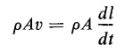
The vector that represents the area of a surface is normal to that surface. In the case of the wire under discussion the cross-sectional area A is at right angles to the length l, i.e., at right angles to the direction of drift. As a result there is no angular displacement between the vector A and the vector dl, and their magnitudes can be multiplied directly so that we have
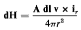
The contribution that this incremental charge makes to the magnetic field intensity at P is expressed in vector form, according to Eq. 3-2, by
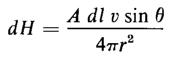
From Eq. 3-1 the magnitude of the vector dH is found to be
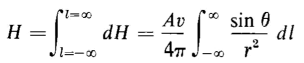
The total magnetic field intensity H at P results from the current in the entire length of the filament and the magnitude of H is found by carrying out the following integration
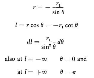
Since r and Θ are functions of l the expressions in Eq. 3-8 can be simplified as follows
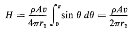
When these relationships are used in Eq. 3-8 the result is
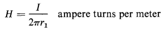
The magnetic field intensity H is most conveniently expressed as a function of current and is generally more useful in that form than in the form of Eq. 3-9. Accordingly
where v = dl/dt, i.e., the velocity at which the resultant charge is moving along the filament. A comparison of Eq. 3-10 with Eq. 3-5 shows that
However, an electric current is defined by
and Eq. 3-9 can be reduced to
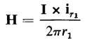
Although the current I is a scalar quantity it can be handled as a vector quantity when it is directed along a path and when the direction of the path is taken into account. In the case of the filament the current is directed along the length l of the filament and the magnetic field intensity at P can be expressed in vector form as follows
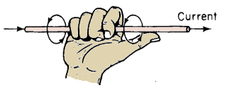
The vector notation of Eq. 3-14 shows that the direction of the magnetic field intensity at P is into the plane of the page when the direction of the current is shown as in Fig. 3-2. Equations 3-13 and 3-14 both show that the magnetic field intensity is constant at all points that are at a constant radial distance from the filament resulting in a magnetic field that is circular and concentric with the filament. The vector notation in Eq. 3-14 shows a cross-product that is merely a shorthand way of expressing the right-hand rule, which states that if the filament is grasped in the right hand, with the thumb pointing in the direction of the current as illustrated in Fig. 3-3, the fingers show the direction of the magnetic field.
The relationship expressed by Eq. 3-14 is valid for long straight conductors of any finite cross-section when the distance r1 is large relative to the cross-sectional dimensions. It is valid for the magnetic field produced by a long straight cylindrical conductor at all points external to the conductor itself.
|
|||||||||||||||||||||||||||||
| Home Magnetic Circuits Magnetic Field About a Straight Wire |
|
||||||||||||||||||||||||||||


Last Update: 2011-01-07