| Capacitors, Magnetic Circuits, and Transformers is a free introductory textbook on the physics of capacitors, coils, and transformers. See the editorial for more information.... |

|
Home  Magnetic Circuits Iron and Air Magnetic Circuits Iron and Air |
|||||||||


|
  |
||||||||
Iron and Air
Many magnetic structures include one or more air gaps. There are air gaps between the rotor and stator of motors and generators. Relays depend upon a change in the length of air gap as do solenoids of the plunger and clapper types. In such circuits the exciting winding must develop sufficient mmf to overcome not only the reluctance of the iron but also that of the air gap.
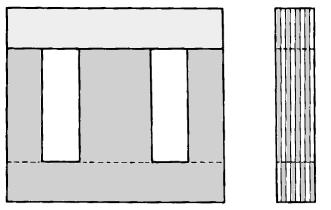
Air gaps are undesirable in magnetic circuits where low mmf are required for given values of flux. This is true of power transformers where a low value of exciting current is desirable. However, the cost of keeping air gaps short or entirely eliminated must not be so great as to outweigh other factors such as cost and difficulty of construction. Air gaps can be eliminated by using punchings in the form of hollow discs, as for example in the toroidal core of Fig. 3-9(a). This construction is practical for small cores, but the cost of dies becomes prohibitive beyond a certain limited size. Figure 3-15 shows a group of small magnetic cores in toroidal form. A construction frequently used for reasons of low cost has the core made up of E and I laminations as shown in Fig. 3-20.
The least laborious method for assembling such a core is to stack all the I laminations together to the desired thickness and all the E laminations together and then pushing the two stacks together. This, however, produces three butt joints where the I stack meets the three legs of the E stack and a small air gap results at each joint. The effect of these joints can be minimized by going to lap joints and assembling the I pieces one at a time with the E pieces in such a fashion that for successive layers the position of the I pieces alternates between top position and bottom position, and the corresponding E pieces between bottom position and top position. Thus, the gap in each layer is bridged by a solid piece of lamination on each side of the gap, as shown in Fig. 3-20. Lap joints can also be achieved by using L-shaped laminations for making up a two-legged core. Some two-legged cores are constructed from straight I-shaped laminations and using lap joints. There are applications, however, in which an air gap is desired in a core to give a smaller variation of inductance with current or to prevent saturation of transformer cores. An air gap is also desired in the cores of chokes when direct current is present.
|
|||||||||
| Home Magnetic Circuits Iron and Air |
|
||||||||


Last Update: 2011-08-01