| Capacitors, Magnetic Circuits, and Transformers is a free introductory textbook on the physics of capacitors, coils, and transformers. See the editorial for more information.... |

|
Home  Magnetic Circuits Graphical Solution for Simple Magnetic Circuit Magnetic Circuits Graphical Solution for Simple Magnetic Circuit |
|||||||||||


|
  |
||||||||||
Graphical Solution for Simple Magnetic Circuit with Short Air Gap
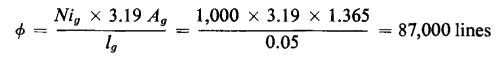
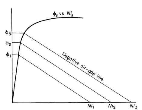
In simple structures with an air gap, such as that shown in Fig. 3-19, it is a relatively easy matter to determine the mmf for a given value of magnetic flux when leakage can be neglected. For the condition of negligible leakage the flux in the air gap is the same as that in the iron. It is therefore necessary only to compute the mmf for the iron for the given value of flux and the mmf for the air gap at the same value of flux. The sum of these mmf gives the total. However, in the case of a given magnetic structure of iron and air, if the total mmf is given and it is required to determine the magnetic flux, the procedure is not quite as straightforward, since the characteristic of the iron is nonlinear. Nevertheless, such calculations can be facilitated by graphical methods. In one of these the flux vs magnetomotive characteristic is plotted for the iron and the negative air-gap line of flux vs mmf is plotted on the same graph. This is illustrated in Example 3-4.
The flux for other values of total mmf can be obtained simply by shifting the air-gap line parallel to itself so that it intersects the desired value of mmf on the abscissa as shown in Fig. 3-22.
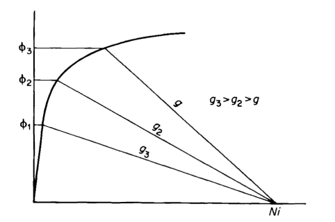
air gap lengths. On the other hand, if it is desired to determine the flux for a given value of mmf but for various lengths of air gap, the different air-gap lines are drawn from the intersection of the mmf on the abscissa as shown in Fig. 3-23. Figures 3-22 and 3-23 apply only to fairly simple structures. As magnetic structures become more complex the calculations accordingly become more involved.
|
|||||||||||
| Home Magnetic Circuits Graphical Solution for Simple Magnetic Circuit |
|
||||||||||


Last Update: 2011-02-16