| Capacitors, Magnetic Circuits, and Transformers is a free introductory textbook on the physics of capacitors, coils, and transformers. See the editorial for more information.... |

|
Home  Magnetic Circuits Energy Stored in Magnetic Circuits Magnetic Circuits Energy Stored in Magnetic Circuits |
|||||||||||||||||||||||||||||


|
  |
||||||||||||||||||||||||||||
Energy Stored in Magnetic Circuits
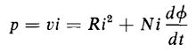
Several examples of energy storage were discussed in Chapter 1. One of these is the R-L circuit for which it was shown that, in building up a current in such a circuit, energy equal to Li2/2 is stored in the inductance. Self-inductance is a property of magnetic circuits and the energy stored in a constant self-inductance is the energy delivered to the magnetic field of the circuit. The power input to the winding on the toroid is obtained by multiplying both sides of Eq. 3-51 by the current i, and we have
where Ri2 = power converted into heat
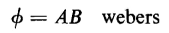
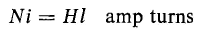
In problems dealing with magnetic forces and core losses, i.e., hysteresis and eddy-current losses, it is usually convenient to determine these quantities in terms of the flux density B. If in the toroid of Fig. 3-9(a), the ratio of R2/R1 does not differ too much from unity, i.e., if the radial thickness of the toroid is small in comparison with the mean radius (R1 + R2)/2 then the flux density B is nearly uniform over the cross section of the core. Then
where A is the cross-sectional area of the core. Also
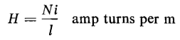
or
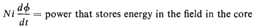
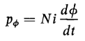
where l = π(R1 + R2)/2, the mean length of the core. The power that stores energy is expressed by
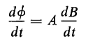
and from Eq. 3-53
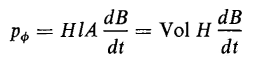
From Eqs. 3-55, 3-56, and 3-57, there results
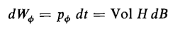
where Vol = volume of the core in cubic meters. The energy input into the magnetic field during the differential time interval dt is
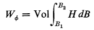
The energy put into the field as the flux density is changed from a value B1 to any other value, B2 is
If the relationship between B and H is linear, i.e., μ is constant
and Eq. 3-60 becomes
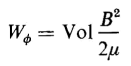
If the flux density B is increased from zero the energy stored in the field is
Equation 3-62 can also be expressed as
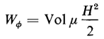
or
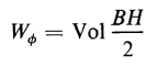
It should be noted that if H is expressed in the ampere turns per unit length in any system and B is in webers per unit area in the same system, and if the volume is calculated in the same units, Eq. 3-64 expresses the energy in joules for that volume. In Eq. 3-64 the quantity BH/2 is known as the magnetic energy density. In nonlinear magnetic circuits, i.e., those in which the relative permeability μr is not a constant, the simple relationship for the energy stored in the field expressed by Eq. 3-64 is not valid. For the nonlinear case the energy is expressed by
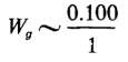
Since it is not practical in most cases to express B as an analytic function of H in nonlinear magnetic circuits the integral in Eq. 3-65 is evaluated by graphical means as discussed in Section 3-25 on magnetic hysteresis. From Eqs. 3-61 and 3-62 it is evident that the lower the value of the permeability μ, the greater is the energy stored in the field for a given value of B. Thus, in a magnetic structure with an air gap, even if quite short, the energy stored in the air gap may be quite large compared with that stored in the iron. Thus, consider the magnetic structure of Example 3-3, in which the mean length of path in iron is 9 in. and the length of air gap is only 0.100 in. From Fig. 3-12 it is found that at a flux density of 80,000 lines per sq in. the relative permeability is approximately 2,200. If fringing is neglected the volume of the air gap is proportional to its length and the energy stored in the gap is
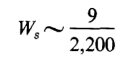
whereas the energy stored in the iron is
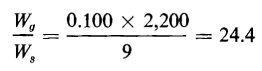
and the ratio of the energy stored in air to that in iron is
Although the air gap has a volume of only 1.1 percent that of the iron, it stores 24.4 times the energy stored in the iron. However, as the iron becomes saturated its permeability decreases and the ratio of the energy in the air gap to that in the iron also decreases.
|
|||||||||||||||||||||||||||||
| Home Magnetic Circuits Energy Stored in Magnetic Circuits |
|
||||||||||||||||||||||||||||


Last Update: 2011-08-01