| Capacitors, Magnetic Circuits, and Transformers is a free introductory textbook on the physics of capacitors, coils, and transformers. See the editorial for more information.... |
|
Home  Magnetic Circuits Demagnetization Curve Magnetic Circuits Demagnetization Curve |
|||||||||||||||||||||||||||


|
  |
||||||||||||||||||||||||||
Demagnetization Curve
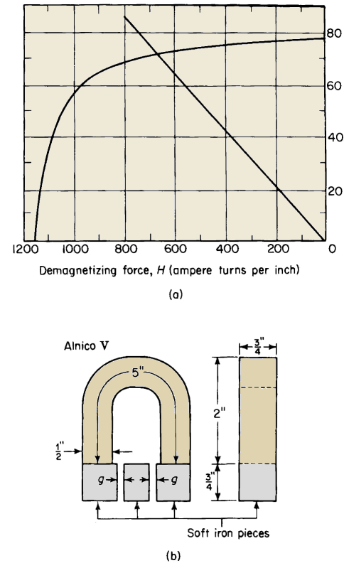
Permanent magnets operate in that region of the hysteresis loop known as the demagnetization curve. The greater the area under the demagnetization curve the more effective is the material in the permanent magnet. Figure 3-29 shows a U-shaped magnet with a soft iron bar, sometimes called a keeper, across its open ends. The magnet is provided with an exciting winding that is usually removed after the magnet has been magnetized. It is common practice to use only one turn with a correspondingly heavy current, which is applied for only a fraction of a second. Let N = the number turns in the winding Suppose that for the condition depicted in Fig. 3-29(a) a current i is applied to the winding such that the magnetizing force is Hmax in Fig. 3-30, which shows the curve for the magnetic material. Then Hmax = NI/l if the reluctance of the horizontal soft iron piece is neglected.
The corresponding flux density throughout the permanent magnet is Bmax if leakage is neglected. If the current is reduced to zero, the magnetizing force becomes zero and the flux density drops from the value Bmax to Br, the retentivity. In order to reduce the flux density to zero it is necessary to apply a current in the reverse direction as shown in Fig. 3-29(b) of such a value as to produce a magnetizing force equal to the coercivity Hc in Fig. 3-30. The portion BRPHC of the curve is known as the demagnetization curve; it represents the region of interest in the operation of permanent magnets.
Suppose that the magnetizing force Hmax has been applied to the magnet with the current in the direction shown in Fig. 3-29(a). Then if the current is reduced to zero, without in the meantime reversing its direction, the flux density will not drop to zero but rather to the value Br as mentioned previously and its direction will remain unchanged. If now a current of such a value as to produce a magnetizing force H in Fig. 3-30 is passed through the winding in the reverse direction as shown in Fig. 3-29(b), the flux density drops from its value of Br to B. It is important to note that although the direction of the current in Fig. 3-29(b) is opposite that in Fig. 3-29(a) the direction of the flux density is the same in both cases. The same magnetic state, i.e., a reduction in the flux density from the value Br to that of B can be produced when there is no current in the winding by introducing an air gap g of the proper length into the magnetic circuit as shown in Fig. 3-29(c), assuming that leakage can be neglected. This can be shown as follows Let lm = the mean length of the permanent magnet The reluctance of the soft iron pieces on both sides of the air gap is neglected. The mmf for the air gap is
and the mmf for the permanent magnet is
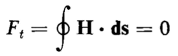
The total mmf Ft around the closed flux path must be the sum of these two mmfs, i.e.
Since for the condition represented by Fig. 3-29(c) there is no current in the exciting winding, the total mmfFt must be zero in accordance with Eq. 3-34. Hence
Then from Eqs. 3-77 and 3-78 there results
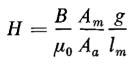
The magnetizing force H for the magnet is obtained in terms of Ha, the magnetizing force for the air gap, by comparing Eqs. 3-75 and 3-76 with Eq. 3-79 and is found to be
which can be expressed by
This relationship is represented graphically by the straight line OP in Fig. 3-30. The values of the magnetizing force H and the flux density B for the permanent magnet are determined by the intersection of the line OP with the demagnetization curve. On the basis of no magnetic leakage the flux must be the same in all parts of the magnetic circuit, i.e., in the permanent magnet, in the soft iron pieces, and in the air gap. The flux is expressed by
|
|||||||||||||||||||||||||||
| Home Magnetic Circuits Demagnetization Curve |
|
||||||||||||||||||||||||||


Last Update: 2011-02-16