| Capacitors, Magnetic Circuits, and Transformers is a free introductory textbook on the physics of capacitors, coils, and transformers. See the editorial for more information.... |

|
Home  Magnetic Circuits Hysteresis Loss Magnetic Circuits Hysteresis Loss |
|||||||||||||||||||||||||


|
  |
||||||||||||||||||||||||
Hysteresis Loss
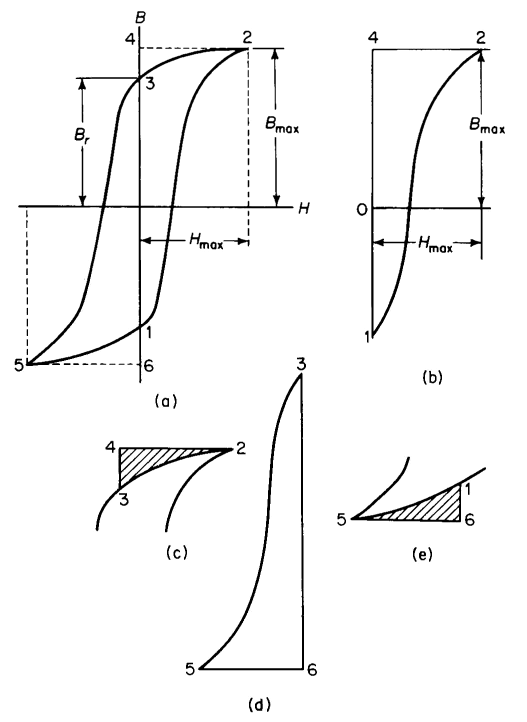
The hysteresis loss results from the B-H characteristic following a different path for decreasing values of H than for increasing values of H. If H is carried through a complete cycle from +Hmax to -Hmax and back to +Hmax, the B-H characteristic becomes a loop known as a hysteresis loop. Figure 3-37(a) shows a typical hysteresis loop.
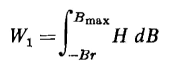
Consider a unit volume of core material. Starting from point 1, Fig. 3-37(b), H is zero and is increased to Hmax; the energy absorbed by the unit volume is
This amount of energy is represented by the area 1-2-4 in Fig. 3-37(b). If H is now decreased from Hmax to 0, the path taken by the B-H characteristic is from point 2 to point 3. The energy is represented by the shaded portion 2-3-4 in Fig. 3-37(c), which is
This energy input is negative since H is positive, but dB is negative, hence W2 represents the energy given up by a unit volume of the core. If H is now taken from zero to -Hmax, the path 3-5 is traced. The energy put into the core material is represented by the area 3-5-6 in Fig. 3-37(d). This area is positive and represents energy absorbed by the core, and
In Eq. 3-90, H is negative and dB is negative and the energy is therefore positive. If H is now increased from -Hmax, the core gives up an amount of energy represented by the shaded area 5-6-1 in Fig. 3-37(e), and
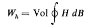
In Eq. 3-91, H is negative and dB is positive, hence the absorbed energy is negative. This means that the core gives up energy. If the sum of the four values of energy is taken with due regard for the signs, whether positive or negative, the total energy is represented by the area of the hysteresis loop in Fig. 3-37(a). Thus, for a core having a volume Yol, and a uniform flux density B throughout the entire volume, the energy loss is
where the line integral represents the area of the hysteresis loop. If H is in ampere turns per unit length and B is in webers per unit area and the volume is in the same system of units, Eq. 3-92 is valid for any system of dimensions. Thus, if H is in ampere turns per inch and B is in webers per square inch, then if the volume Vol is in cubic inches, Wh expresses the energy loss in joules for the entire volume. This is true also if the unit of length is the meter and the volume is in cubic meters. In the case of the flux undergoing a cyclic variation at a frequency f cps there are f hysteresis loops per second, so to speak, and the power is
or
In order to use the area of the loop in Eq. 3-93 it is necessary to take into account the scale to which the loop is plotted on the graph. Let p = the number of units of H per inch of graphthen W = pq  (area of loop in square inches) (area of loop in square inches)
The area of the loop may be determined from planimeter measurements or by counting squares. Then
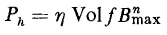
The hysteresis loss, in a volume Vol in which the flux density is uniform and varies cyclically at a frequency of f cps, is expressed empirically as
The nature of the magnetic material determines the values of η and n. The exponent may vary from a value of 1.5 to 2.5 for different materials and is
usually not even constant for the same core. Steinmetz found in 1892 that the exponent n had a value of 1.6 for a range of flux densities from about 1,000 to 12,000 gausses for the magnetic materials then commonly in use. However, this exponent no longer applies to all present day materials. The hysteresis loss can, however, be computed from the area of the hysteresis loop for a given material if there are no re-entrant loops. If, on the other hand, the hysteresis loop has re-entrant loops, their areas must be added to that of the main loop. Re-entrant loops result from a reduction in a positive value of H and then an increase before Hmax is reached. This is shown in Fig. 3-38 where H, after having increased from 0 to a value Ha, is decreased to a value Hb and then increased to Hmax. The locus then is from H = 0 at -Br, to Ha at Ba, back to Hb at Bb, back along the minor loop to Ha at Ba, then along the major loop from a to c at which we have Bmax and Hmax. A similar situation exists in this case in the bottom half of the loop.
Equation 3-96 is not valid for unsymmetrical loops such as occur when there is a d-c component of flux in the presence of a-c flux, a situation that exists in some choke coils and transformers in vacuum tube circuits. An unsymmetrical hysteresis loop is shown in Fig. 3-39.
|
|||||||||||||||||||||||||
| Home Magnetic Circuits Hysteresis Loss |
|
||||||||||||||||||||||||


Last Update: 2011-02-16