| Capacitors, Magnetic Circuits, and Transformers is a free introductory textbook on the physics of capacitors, coils, and transformers. See the editorial for more information.... |

|
Home  Magnetic Circuits Eddy-Current Loss Magnetic Circuits Eddy-Current Loss |
|||||||||||||||||||||||||||||||||||


|
  |
||||||||||||||||||||||||||||||||||
Eddy-Current Loss
From earlier considerations it is evident that a variation in the flux linking a circuit generates an emf in the circuit. This is true also for the ferromagnetic circuit since the flux in the iron must naturally link various parts of the iron. Hence emfs are induced in the iron portions, which in turn produce currents, known as eddy currents, that circulate in the iron. In order to keep the eddy currents within practical values, the iron in the magnetic circuits is laminated, although for some high-frequency applications molded ferrite materials are used in solid form. The laminations are coated with an insulating oxide or, in the case of large transformers, with a coating of insulating enamel. Laminating the core, with the plane of the laminations parallel to the direction of the flux, confines the eddy currents to paths of relatively small cross section and consequently high resistance. Shapes of typical laminations for small and medium size magnetic circuits are shown in Fig. 3-14.
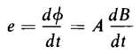
Consider the piece of lamination shown in Fig. 3-41. The thickness of the lamination is τ and the height and width are h and w respectively. In Fig. 3-41 the thickness τ is shown much greater in proportion to h and w than is normally the case. The direction of the magnetic flux is at right angles to the thickness. Let B = the magnetic flux density, considered uniform throughout the lamination. If the flux density varies with respect to time, an emf is induced in the elemental path 1-2-3-4 of Fig. 3-41 by the flux linking this path, and
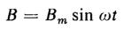
where A = 2 hx, the area of the path 1-2-3-4, This approximation is justified because r is small in relation of A. In the case of most transformers and iron-core chokes the variation of flux with respect to time is sinusoidal or of such a nature that the flux can be expressed as a function of time in a Fourier series, which in general consists of a series of sine and cosine terms. However, let
where ω = 2μf and f is the frequency in cycles per second, and the voltage induced in the elemental path is expressed by
This voltage produces a current in the elemental path that is practically in phase with the voltage because of the relatively high resistance of the path. Let p = resistivity of the lamination; then the resistance of the path is
from
where l = 2h, the length of current path, and A = 2w dx, the cross-sectional area of the current path. Here again the length of the path can be approximated to the value 2h because the thickness τ is so small. The current in the differential path is obtained by dividing the induced voltage in Eq. 3-99 by the resistance of the current path as given by Eq. 3-100, which yields
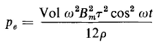
The instantaneous power converted into heat in the elemental path is, by Eqs. 3-99 and 101
and the instantaneous loss through the entire lamination is
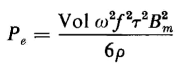
The quantity hwτ in Eq. 3-102 is the volume of the lamination, hence Eq. 3-102 can be rewritten as
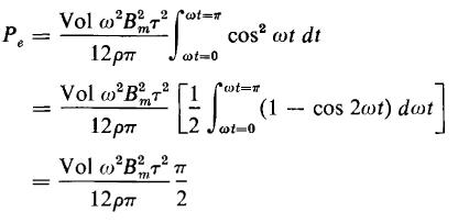
Where Vol = hwτ. Equation 3-103 expresses the instantaneous power. The power read by an ordinary wattmeter is the average power, the quantity of interest here, which is
Substitution of Eq. 3-103 in 3-104 yields
Substituting 2πf for ω in Eq. 3-105 gives
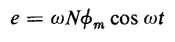
The eddy-current loss can, in some cases, be expressed in terms of the voltage applied to the exciting winding. If the winding that is energized from the a-c source has N turns and all the flux in the core links all of these turns, then the induced voltage is expressed by
and if the flux density in the core varies according to Eq. 3-100, then the flux in the core is expressed by
Equations 3-107 and 3-108 yield
in which the maximum instantaneous voltage is
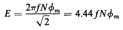
and the effective value of the voltage is
If Ac is the cross-sectional area of the core, then Eq. 3-109 can be rewritten as
Equation 3-110 shows that, for a sinusoidal emf or flux variation, the product fBm is directly proportional to the induced emf E. Hence, the eddy-current losses are directly proportional to E2 as can be seen if we substitute Eq. 3-110 in Eq. 3-106. This results in
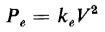
Generally the resistance drop in large transformers and large chokes is so small that the induced emf is very nearly equal to the applied emf V and the eddy-current loss in a given core and winding can be expressed approximately by
|
|||||||||||||||||||||||||||||||||||
| Home Magnetic Circuits Eddy-Current Loss |
|
||||||||||||||||||||||||||||||||||


Last Update: 2011-02-16