| Capacitors, Magnetic Circuits, and Transformers is a free introductory textbook on the physics of capacitors, coils, and transformers. See the editorial for more information.... |

|
Home  Inductance - Electromagnetic Energy Conversion Inductance, Magnetic Reluctance and Permeance Inductance - Electromagnetic Energy Conversion Inductance, Magnetic Reluctance and Permeance |
|||||||||||||||||||||||||||||||||||


|
  |
||||||||||||||||||||||||||||||||||
Inductance in Terms of Magnetic Reluctance and Magnetic Permeance
As mentioned previously, the magnetic circuit is similar in some respects to the electric circuit. In the case of the simple d-c circuit current, voltage and resistance are related to each other, under steady-state conditions, in accordance with Ohm's Law. The same kind of relationship is sometimes applied to magnetic circuits as follows
where
F = magnetomotive force (mmf) in ampere turns (Ni) The relationship expressed by Eq. 4-27 can be stated in terms of the magnetic permeance as follows
where
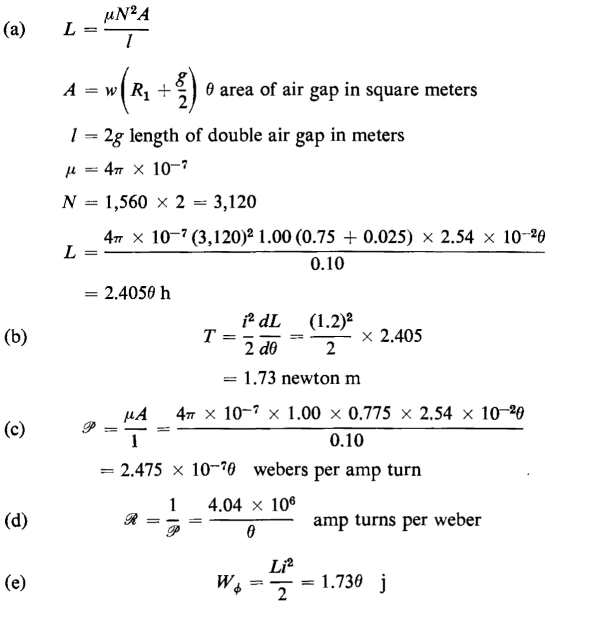
In the case of magnetic circuits in which there is no leakage, all the flux serves to link each turn of the winding and Φ represents the total flux. The magnetic circuit shown in Fig. 3-9 practically satisfies that condition. However, in magnetic circuits where there is magnetic leakage and the flux follows paths such that different amounts of flux link different numbers of turns in the exciting winding, the value of Φ in Eqs. 4-27,4-28, and 4-29 is less than the total flux. Such situations exist in air-core solenoids as well as in many circuits having ferromagnetic cores. Figure 4-3 shows a coil in which the current produces complete and partial flux linkages. The symbol P stands for permeance, which is the reciprocal of reluctance. Magnetic reluctance in these relationships corresponds to resistance in the electric circuit; permeance corresponds to conductance. Both these quantities, reluctance and permeance, are functions of the magnetic permeabilities of the different parts of the magnetic circuit as well as the configurations of these parts. Substitution of Eq. 4-28 in Eq. 4-27 yields
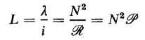
but F = Ni and λ/i = L, hence
from which
For the special case in which all the flux is confined to a path of constant cross-sectional area A and the mean length of flux path is l the expression for the reluctance is reduced to
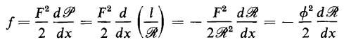
Magnetic pull and magnetic torques can also be expressed as functions of permeance and reluctance from Eq. 4-32
and the developed force can be written as
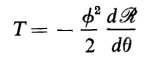
and the developed torque as
The force and torque can be expressed in terms of reluctance by replacing P with 1/R in Eq. 4-36, thus
and
In Eqs. 4-35 to 4-38 the expressions for force and torque are those developed by the electromagnetic structure, in other words, motor action is involved when there is motion of translation or rotation in the direction of the developed forces.
|
|||||||||||||||||||||||||||||||||||
| Home Inductance - Electromagnetic Energy Conversion Inductance, Magnetic Reluctance and Permeance |
|
||||||||||||||||||||||||||||||||||


Last Update: 2011-01-14