| Capacitors, Magnetic Circuits, and Transformers is a free introductory textbook on the physics of capacitors, coils, and transformers. See the editorial for more information.... |

|
Home  Inductance - Electromagnetic Energy Conversion Mutual Inductance Inductance - Electromagnetic Energy Conversion Mutual Inductance |
|||||||||||||||||||||||||||||||||||||||||||||


|
  |
||||||||||||||||||||||||||||||||||||||||||||
Mutual Inductance
Section 4-1 described mutual inductance as a parameter that is associated with the flux linkage produced in one circuit by the current in another circuit.
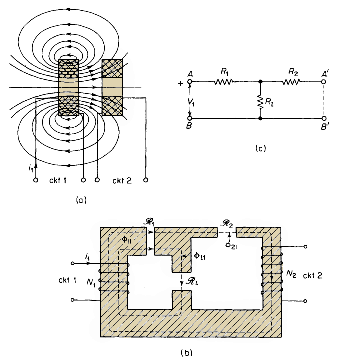
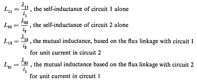
Quantitatively, the mutual inductance between two circuits may be defined as the flux linkage produced in one circuit by a current of one ampere in the other circuit. In this discussion a circuit is considered as having one or more turns. Figure 4-4 shows a schematic diagram of two circuits that are coupled inductively, i.e., magnetic flux from one circuit links the other circuit. A current i1 in circuit 1 produces magnetic flux, some of which links some of the turns of circuit 2 and thus induces a voltage in circuit 2 when i1 changes. Let λ11 = flux linkage of circuit 1 produced by its own current i1 The unit of flux linkage is the weber turn and that of inductance is the henry, which can be expressed as a weber turn per ampere. Hence
The two circuits and the effect of magnetic coupling between them can be represented by the equivalent magnetic circuit and the windings N1 and N2 in Fig. 4-4(b), where N1 and N2 are the numbers of turns in circuits 1 and 2. Three air gaps having reluctances R1, R2 and R1 are shown in the magnetic circuit, the shaded portion of which is assumed to have infinite permeability and, consequently, zero reluctance. The resistivity of the material in the shaded portions is considered infinite so that no eddy currents can flow. Assume a current of i1 to flow in circuit 1 while the current in circuit 2 is zero. Let Φ11 be an equivalent flux, which, in linking all N1 turns of circuit 1, produces the flux linkage λ11. Then
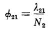
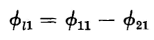
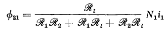
In Fig. 4-4(b) the equivalent flux Φ11 is shown as having two components, Φ21 and Φ11, in which Φ21 is the equivalent flux that, in linking all N2 turns of circuit 2, produces the flux linkage λ21. Therefore
The remaining component Φ11 is the equivalent leakage flux of circuit 1 linking all N1 turns without linking any of the N2 turns of circuit 2. This means that
The magnetic circuit of Fig. 4-4(b) is comparable to the electric circuit of Fig. 4-4(c), which is the equivalent T-circuit for any 3-terminal arrangement of pure resistances. The resistances R1, R2, and R1 correspond to the reluctances R1, R2 and R1 of the magnetic circuit, whereas the applied voltage V1, is analogous to the mmf N1i1 produced by the N1-turn winding. Therefore, it is evident, on the basis of elementary electric circuit theory, that
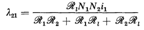
and that resulting flux linkage produced in circuit 2 by i1 is
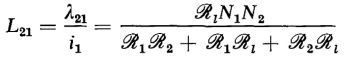
The mutual inductance based on the flux linkage with circuit 2 due the current in circuit 1 is therefore
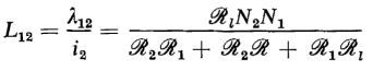
The mutual inductance L12, based on the flux linkage with circuit 1 due the current in circuit 2, can be found by considering a current i2 in circuit 2 while the current i1 in circuit 1 is zero, and then going through the process used previously, or simply by interchanging the subscripts 1 and 2 in Eq, 4-43. This results in
Equations 4-43 and 4-44 show the mutual inductance between two electric circuits to be reciprocal when the circuits are coupled by a homogeneous magnetic medium of constant permeability, i.e.
In cases where there are only two magnetically coupled circuits, the letter M is used to represent mutual inductance, i.e.
Coefficient of coupling The mutual inductance between two circuits can be expressed in terms of their self-inductances L11, L22 and their coefficient of coupling k, which is a function of the reluctance of the leakage flux path. It can be seen from Eq. 4-44 that for given values of R1 and R2 the mutual inductance increases with the reluctance R1 of the leakage path, becoming a maximum when R1 approaches infinity, the condition for perfect magnetic coupling between the two circuits. Let
and
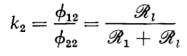
from which the coefficient of coupling is, by definition
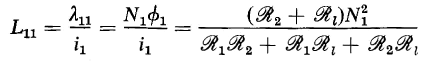
The self-inductance of circuit 1 is
and that of circuit 2 is
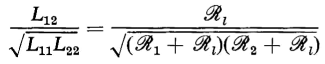
The relationship between the mutual inductance and the self-inductances is given by the ratio, based on Eqs. 4-44, 4-49, and 4-50.
A comparison of Eqs. 4-48 and 4-51 shows the mutual inductance to be
The coefficient of coupling k cannot exceed unity, although values as high as 0.998 are not unusual in iron-core transformers, whereas k in air-core transformers is generally smaller than 0.5. Energy in the field of coupled circuits The electromagnetic differential energy supplied to an electric circuit carrying a current i is given by
It should be remembered that electric energy over and above that required to supply the irreversible energy dissipated in the form of heat is required to maintain current in a circuit that is subjected to a variation of flux linkage. This is true whether the flux linkage λ is produced only by the current i in the circuit itself, or whether it is produced only by magnetic fields from other sources, or by fields from its own current in combination with those from other sources. The electromagnetic differential energy input to two magnetically coupled circuits is
where
from which
If there is no motion of one circuit relative to the other, and if there is no change in the configuration of the magnetic circuit, the self-inductances L11 and L22 as well as the mutual inductance M are constant, and no mechanical energy is supplied to or abstracted from the field. It is assumed, of course, that the inductances are independent of the currents i1 and i2 i.e., that the magnetic circuit is linear. Equation 4-56 can, therefore, be reduced to the form
Since this is also the differential energy stored in the field
and the energy present in the field due to the currents i1 and i2 is
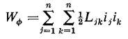
Although the inductances were assumed constant while the currents were increased from zero to i1 and i2 in circuits 1 and 2, Eq. 4-58 expresses the energy stored in the field for the particular values of L11, L22, M, i1 and i2 whether the inductances are constant or variable. This means that the energy stored in the field, for given values of L11, L22, M, i1 and i2, is unaffected by previous values these inductances might have had. The development that led to Eq. 4-58 can be generalized to include n instead of two magnetically coupled circuits expressing the energy stored in the field by
|
|||||||||||||||||||||||||||||||||||||||||||||
| Home Inductance - Electromagnetic Energy Conversion Mutual Inductance |
|
||||||||||||||||||||||||||||||||||||||||||||


Last Update: 2011-02-16