| Capacitors, Magnetic Circuits, and Transformers is a free introductory textbook on the physics of capacitors, coils, and transformers. See the editorial for more information.... |

|
Home  Inductance - Electromagnetic Energy Conversion Forces in Nonlinear Magnetic Circuits Inductance of Magnetic Circuits Containing Iron Inductance - Electromagnetic Energy Conversion Forces in Nonlinear Magnetic Circuits Inductance of Magnetic Circuits Containing Iron |
|||||||||||||||||||


|
  |
||||||||||||||||||
Inductance of Magnetic Circuits Containing Iron
The concept of inductance when applied to nonlinear magnetic circuits leads to inconsistencies, depending upon how inductance is defined. The self-inductance of a circuit is defined in several ways, all of which are consistent in the case of air-core circuits. These are first
second
and third
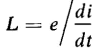
In Equation 4-70, WΦ is the energy stored in the magnetic field. The emf of self-induction is also expressed by
Another expression for self-inductance is obtained when Eq. 4-71 is substituted in Eq. 4-69, namely
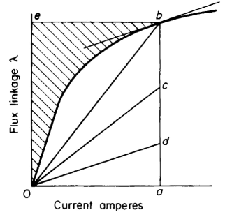
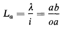
Equations 4-68, 4-70, and 4-72 do not yield the same values of inductance in a magnetic circuit containing iron or other ferromagnetic materials. This is particularly evident when there is appreciable saturation of the magnetic material. Figure 4-6 shows the magnetization curve of a magnetic circuit containing iron. Such a curve is typical of a-c and d-c rotating machines, chokes, transformers, and other electromagnetic devices. Let the self-inductance be evaluated on the basis of Eqs. 4-68, 4-70, and 4-72 for this magnetic circuit when the flux linkage λ has the value ab in Fig. 4-6. The current required for this value of flux linkage is oa amp. Then, on the basis of Eq. 4-68, the apparent self-inductance is
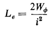
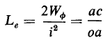
and, on the basis of Eq. 4-70, the effective self-inductance is
The shaded area in Fig. 4-6 corresponds to WΦ in Eq. 4-70. The line oc is constructed so that the area of the triangle oac equals this shaded area. Hence
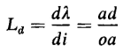
Finally, on the basis of Eq. 4-72, the differential self-inductance is
The line od is drawn parallel to the tangent at the point b and has a slope of dλ/di. It is apparent, from Eqs. 4-73, 4-74, and 4-75, that three different values of inductance are obtained in the same nonlinear circuit for a given current when three basic definitions of self-inductance are applied, although all three definitions lead to the same value for linear magnetic circuits. In spite of these inconsistencies, Eqs. 4-73, 4-74, and 4-75 lead to adequate approximations in many cases. Certain analyses of the steady-state performance of synchronous machines make use of the relationship expressed by Eq. 4-73, whereas in the cases of chokes and transformers, in which small amounts of a-c flux are superimposed on a relatively large value of d-c flux, the differential inductance in Eq. 4-75 is useful. Equation 4-74 leads to a value of inductance that is convenient, for example, as a guide for evaluating the duty imposed upon contacts in switches or circuit breakers that interrupt the current in inductive circuits. Generally, however, the problem of the nonlinear magnetic circuit is approached from standpoints that avoid the use of inductance in the analysis and instead make use of the magnetization curve. The analysis of forces and torques in nonlinear magnetic circuits is a case in point that makes use of the magnetization curve.
|
|||||||||||||||||||
| Home Inductance - Electromagnetic Energy Conversion Forces in Nonlinear Magnetic Circuits Inductance of Magnetic Circuits Containing Iron |
|
||||||||||||||||||


Last Update: 2011-01-16