| Capacitors, Magnetic Circuits, and Transformers is a free introductory textbook on the physics of capacitors, coils, and transformers. See the editorial for more information.... |

|
Home  Inductance - Electromagnetic Energy Conversion Forces in Nonlinear Magnetic Circuits Force and Energy Relationships Inductance - Electromagnetic Energy Conversion Forces in Nonlinear Magnetic Circuits Force and Energy Relationships |
|||||||||||||||||||||||||||||||||||||||||||||||||||


|
  |
||||||||||||||||||||||||||||||||||||||||||||||||||
Force and Energy Relationships Based on the Magnetization Curve
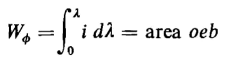
The energy stored in the magnetic field of the circuit, which has the magnetization curve shown in Fig. 4-6, is represented by the shaded area, i.e.
The area oba under the magnetization curve is also a product of flux linkage and current and represents the coenergy, i.e.
In linear magnetic circuits the energy stored in the field and the coenergy are equal, whereas in nonlinear magnetic circuits the coenergy is greater than the stored energy, as can be seen from Fig. 4-6. Consider the rotary electromagnet shown in Fig. 4-7(a). Since there is only one winding (that on the stator), the flux linkage can be plotted against the current in that winding as in Figs. 4-7(b) and 4-7(c).
Linear Operation (Unsaturated Region). Suppose that the excitation of the electromagnet is held to values low enough so that the iron remains unsaturated so that the reluctance of the iron is negligible in comparison with that of the air gap. Then, for the angle Θ1 between the magnetic axis of the rotor and an arbitrary reference line through the center of the rotor, the magnetization curve is represented to a good degree of approximation by the straight line ob in Fig. 4-7(b). If the angle is increased from Θ1 to Θ2 = Θ1 + ΔΘ, the reluctance of the air gap is decreased and the magnetization curve is then represented by the straight line od. Now if the current i is held constant at the value oa in Fig. 4-7(b) while the displacement angle is increased from θ1 to θ2, the flux linkage increases from λ1 to λ2 = λ1 + Δλ and the electromagnetic energy input is
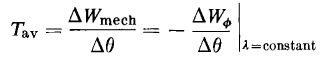
and is represented by the area of the rectangle bced. The energy originally stored in the field, i.e., for the angle Θ1, is represented by the area of the triangle obc, and when the area of the rectangle bced is added, the area obdeo is obtained. The final energy stored in the field, i.e., for the angle Θ2, is represented by the area of triangle ode, and when this area is subtracted from the area obdeo, the result is the area of triangle obd, which must represent the mechanical energy. The area of triangle obd is one-half that of rectangle cbde, which shows that, for constant current in a linear magnetic circuit, the mechanical energy output equals one-half the electromagnetic energy input, as was shown in the derivations making use of variation in inductance with displacement. If the flux linkage is held constant while the rotor is advanced through the angle Δθ, the current i decreases from oa to og in Fig. 4-7(b). Furthermore, the the electromagnetic energy input is zero when the flux linkage is constant. The energy stored in the field, when the angle is θ2, is represented by the area of the triangle ofc and the mechanical energy output by the triangle obf. The mechanical energy when the flux linkage is constant is therefore abstracted from the energy stored in the field. The average torque that is developed when the current is constant while the displacement Δθ occurs is
and for the case of constant flux linkage
The same considerations, as far as force is concerned, apply to electromagnets in which the displacement is linear, say Δx. In that case, Δx is substituted for Δθ in Eqs. 4-79 and 4-80. The areas of the triangles must, of course, be in terms of flux linkage and current. Thus, the area of triangle obd would be one half the product of Δλ or λ2 - λ1 and oa in amperes. Nonlinear Operation (Saturated Region). If the current in the exciting winding is increased to a value represented by oa' so that the iron becomes saturated as shown in Fig. 4-7(c), the magnetization curves for the rotor positions at Θ1 and Θ2 are no longer linear. The graphical analysis, nevertheless, may be applied just as in the case of linear operation. If the current is held constant while the rotor undergoes a change in angular displacement of ΔΘ = Θ2 - Θ1 the flux linkage increases from λ'1 to λ'2 or by an amount Δλ' and the electromagnetic input is
which is represented by the area of the rectangle c'b'd'e'. The energy stored in the field changes by an amount corresponding to the difference between the areas od'e'o for Θ2 and ob'c'o for Θ1 The mechanical energy output is then represented by the area ab'd'o. Similarly, if the flux linkage is held constant during the rotor displacement ΔΘ, the mechanical energy output is represented by the area ob'f'o since there is no electromagnetic energy input, and we have
where WΦ1 and WΦ2 is the energy stored in the field at Θ1 and Θ2 for λ' constant at λ'1. The average developed torque when the flux linkage is held constant must therefore be
On the other hand, when the current is held constant, the mechanical energy output equals the increase in the coenergy (area ob'd'o), and for constant current the average torque is
The difference between the areas ob'd'o for constant current and ob'f'o is the area f'b'd', which becomes smaller and smaller as ΔΘ is made smaller, vanishing as ΔΘ
It is important to note that when the energy WΦ can be expressed analytically it must be explicitly in terms of the flux linkage λ and the angular position Θ, whereas the coenergy W'Φ must be expressed explicitly in terms of the current i and the angular position Θ. This follows from the fact that the energy stored in the field is given by
and the current to produce a given value of flux linkage λ is determined not only by the value of λ, but also by that of the parameter Θ, so that the current is expressed implicitly by
Also, the coenergy is obtained as follows
in which the flux linkage is a function of the current and Θ, or
It should be carefully noted that Eq, 4-84 expresses the developed torque, the direction being such as to decrease the stored energy for a given value of λ, as indicated by the minus sign, or such as to increase the coenergy for a given value of i In systems where translational rather than rotary displacement occurs, the developed force is
As mentioned previously, the stored energy and the coenergy are equal in linear systems. Then, on basis of Eq, 4-79, the torque, as ΔΘ
or, in translational systems
Various torque and force relationships can be derived for linear systems on the basis of Eqs. 4-86 and 4-87 since the energy stored in the field, whether the system is linear or not, is determined from the integral
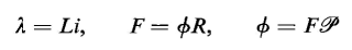
The following relationships obtain for linear systems
so that the energy stored in the field can be written as
and the torque can be expressed as
and the force can be written as
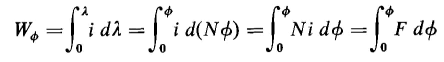
Various relationships for torque and force can be derived for linear systems on the basis of Eqs. 4-86 and 4-87 since the energy stored in the field (whether the system is linear or nonlinear) is given by
where Φ is the equivalent flux linking all N turns and F = Ni. However, for linear systems
and when Eq. 4-91 is substituted in 4-90, the result is
Then, from Eqs. 4-86, 4-87, and 4-92, the torque and force are
and
Equations 4-93 and 4-94 show that the developed torque and developed force are in a direction such as to increase the energy stored in the field if the current is held constant. In other words, the forces on the members of the system are such as to increase the flux linkage if the current remains constant. In the case of a solenoid, the force is such as to shorten the length of the air gap, i.e., dP/dx is positive and dR/dx is negative since the permeance is inversely proportional to the length of the air gap and the reluctance is directly proportional to the gap length. It is necessary when performing the partial differentiation of Eqs. 4-93 and 4-94 to express the stored energy WΦ in terms of the current i or the mmf F rather than the flux Φ. For example, since F = ΦR the energy stored in the field is
and if the partial derivative is taken of WΦ the result is
When this result is compared with that in Eq. 4-94, it will be found that the signs are opposite. This is to be expected since, in taking the partial derivative of the stored energy with respect to Θ, the flux Φ is a parameter assumed constant. Also, a decrease in the reluctance is accompanied by a decrease in the energy stored on the field, whereas, for constant current, a decrease in the reluctance is accompanied by an increase in the stored energy.
Since the units for flux linkage and mmf are the weber turn and the ampere turn, the energy stored in the field can also be represented by
so that Eq. 4-85 can be put into the form
Although the relationships offeree and torque to the variation of the energy stored in the magnetic field with variation in displacement were derived for singly excited systems, these relationships can be extended to multiply excited systems (in which more than one winding is excited) as shown by White and Woodson. The force is then expressed by
or
|
|||||||||||||||||||||||||||||||||||||||||||||||||||
| Home Inductance - Electromagnetic Energy Conversion Forces in Nonlinear Magnetic Circuits Force and Energy Relationships |
|
||||||||||||||||||||||||||||||||||||||||||||||||||


 0, so that torque is expressed by


Last Update: 2011-01-16