| Capacitors, Magnetic Circuits, and Transformers is a free introductory textbook on the physics of capacitors, coils, and transformers. See the editorial for more information.... |

|
Home  Saturable Reactors Single-Core Saturable Reactor Saturable Reactors Single-Core Saturable Reactor |
|||||||||||||||||||||||||||||


|
  |
||||||||||||||||||||||||||||
Single-Core Saturable Reactor With Premagnetization
Saturable reactors that are used for controlling variable outputs are provided, in their simplest form, with a d-c winding that furnishes the premagnetization and with an a-c winding between an a-c source and a load to which the current is controlled by varying the amount of premagnetization.
Figure 7-5 is a schematic diagram of a single-core reactor with a d-c control winding of Nc turns and an a-c output winding, also known as the gate winding, of NG turns. The core shown in Fig. 7-5 is rectangular; it may, however, be toroidal or any other convenient shape. To insure good efficiency and good regulation, the resistance of both windings must be low when referred to the load impedance. This means that unless the impedance of the control circuit or premagnetizing circuit is kept above a certain value by using, for example, an external choke coil, the control circuit will act as a short-circuited secondary with the a-c winding as the primary. Therefore, without a high impedance in the control circuit, the impedance of the reactor, viewed from the a-c winding, would be low, being practically equal to the leakage impedance. Consequently, the d-c component in the control winding would lose much of its effect on the output current, since the leakage flux paths are largely in air. A reactor or choke in series with the control circuit is a means for suppressing the a-c component of current in the control winding. Such a choke, if it is to be of reasonable size, must have a ferromagnetic core with an air gap to prevent saturation from the direct current. Even so, the size of the choke is comparable to that of the single-core saturable reactor itself. Practically all of the a-c voltage induced in the d-c winding appears across the choke coil.
Where RG is the resistance of the a-c winding of the reactor and the voltage of the a-c source is
It therefore appears that the saturable reactor affords a means of adjusting the output current from a very low value to a maximum of
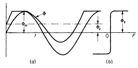
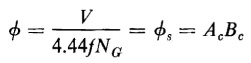
Although a large range of output current is possible, the wave form of the current, while practically sinusoidal at maximum output, is quite distorted at the smaller outputs. To demonstrate this, let the amplitude of the a-c flux be just below the saturated value Φs when there is no premagnetization. Then the output current is zero and the entire voltage of the a-c source is impressed on the a-c winding of the reactor. And if the resistance of that winding is neglected, the amplitude of the a-c flux as shown in Fig. 7-6(b) is
The output current for this condition is zero. When direct current is applied to the control winding, output current is furnished to the load. Because of the choke, the current in the control winding under steady-state conditions is
where Vc is the d-c source voltage and Rc the resistance of the control circuit including the choke. In the unsaturated interval, the total mmf must be zero, and if NG and Nc are the turns in the output and control windings with ia the current in the output winding, then for the current directions shown in Fig. 7-1, the output current is
During the saturated interval the voltage induced in the a-c winding is zero, and the output current is
where the source voltage is given by
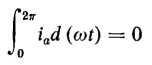
Since there is no d-c component in the voltage of the output circuit, there can be no d-c component in the output current under steady conditions, and the average value of the output current over a complete cycle must be zero, i.e.
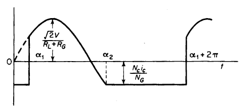
On the basis of Eqs. 7-12, 7-13, and 7-14, the wave form of the output current is as shown in Fig. 7-7, from which it is found that
The left-hand side of Eq. 7-15 represents the area under the positive portion of the current wave and the right-hand side of the area above the negative
portion of the current wave. The angle α1 is the firing angle, i.e., the value of ωt at which the flux reaches the saturated value Φs, and α2 is the angle at which the iron becomes unsaturated. When the integrations in Eq. 7-15 are performed, there results
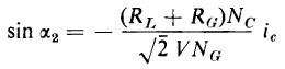
From Fig. 7-7 it is apparent that
or
Substitution of Eq. 7-17 in Eq. 7-16 yields
The angle α1 can be evaluated from Eq. 7-18 by graphical methods or by means of suitable approximations. It is important to remember that the results achieved in the equations above are based on the amplitude of the a-c flux Φm being just below the saturated value Φs. The single-core premagnetized saturable reactor is seldom used because the wave form of the output current is unsymmetrical over a large part of the operating range. In addition, because of the choke in the control circuit, there is the disadvantage of a high time constant, where speed of response is important.
|
|||||||||||||||||||||||||||||
| Home Saturable Reactors Single-Core Saturable Reactor |
|
||||||||||||||||||||||||||||


Last Update: 2011-02-16