| Capacitors, Magnetic Circuits, and Transformers is a free introductory textbook on the physics of capacitors, coils, and transformers. See the editorial for more information.... |

|
Home  Saturable Reactors Gate Windings in Parallel Saturable Reactors Gate Windings in Parallel |
|||||||||||||||||


|
  |
||||||||||||||||
Gate Windings in Parallel
The gate windings of both saturable reactors in Figs. 7-8(a) and 7-8(b) are shown connected in parallel, which means that the voltage impressed on one must equal that impressed on the other.
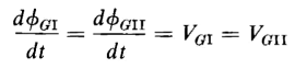
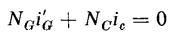
Components of flux If the resistances of the windings are neglected, the voltages induced in the two gate windings must equal each other, and if ΦGI and ΦGII are the fluxes linking gate windings I and II, we have
The voltages induced in the control windings of Fig. 7-8(a) are equal and opposite, cancelling each other, thus eliminating the need for a choke in the control circuit, as required in the single-core reactor. In the case of the 3-legged reactor of Fig, 7-8(b), the voltages induced in the control winding by the fluxes linking the two gate windings also cancel each other. As a result, there is no a-c component in the current of the control circuit, so that ic, the control current, is strictly d-c for steady-state operation when the gate windings are connected in parallel and when their resistance is appreciably lower than that of the control circuit.
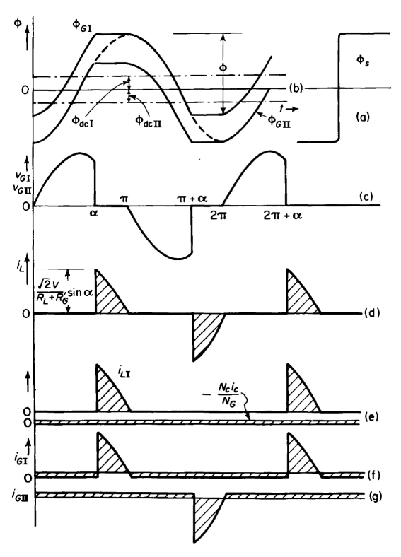
Again, assume the magnetization curve for the cores to be as shown in Fig. 7-9(a) and the amplitude of the a-c flux, at zero premagnetization, to be just below the saturated value Φs. At zero premagnetization, the control current ic is zero and the zero axes of the a-c fluxes linking the two gate windings coincide. However, when there is d-c premagnetization, the zero axis for the a-c component ΦacI linking gate winding I is shifted upward, and the component ΦacII linking gate winding II is shifted downward, as shown in Fig. 7-9(b) for the polarities shown in Fig. 7-8. In the case of premagnet-ization, the a-c fluxes, although periodic, are not sinusoidal since the maximum value of the combined a-c and d-c fluxes cannot exceed the saturated value Φs. If ΦGI and ΦGII are the total fluxes linking gate windings I and II, we have
where ΦacI and ΦacII are the a-c components andΦdcI and ΦdcII are the d-c components of flux linking the respective gate windings. The control current ic is assumed to be a constant direct current, a condition that is satisfied if the equivalent resistance (NG/NC)2 Rc of the control circuit is much greater than the resistance 2RG of the gate windings. The gate windings carry an unsymmetrical alternating current that contains no net d-c component as shown in Figs. 7-9(f) and (g). Then, for a given direct current in the control winding, the d-c flux components must be constant, and substitution of Eq. 7-20 in Eq. 7-19 yields
which can be satisfied only if the a-c flux components linking the gate windings are equal, i.e.
since the a-c fluxes themselves can contain no constant term. The d-c fluxes must equal each other because they are produced by equal mmfs in identical cores. Hence
as shown in Fig. 7-9(b). At the firing angle α, the flux ΦGI in core I reaches the saturated value Φs and remains there until the instantaneous a-c voltage reverses its polarity, i.e., at ωt = π. The voltage across the gate windings is therefore zero, since ΦGII also remains constant over the interval α < ωt < π. The a-c supply voltage during that interval is impressed across the load resistance. This action produces the wave form of the load voltage as shown in Fig. 7-9(d). Because the load is noninductive, the current through it has the same wave form as the load voltage. The mechanism that holds the flux constant in the unsaturated core during the conducting angle is explained as follows: During the conducting period, in which core I is saturated, the emf induced in its gate winding and control winding is zero and both of these windings, then, are short circuits if their resistances are neglected. Therefore, control winding I acts as a short circuit on control winding II, which in turn acts as the secondary, while gate winding II acts as the primary of an ideal transformer that has its core unsaturated. Since core II is unsaturated while the constant control current ic is flowing, there must be a corresponding current i'G in gate winding II such that the resultant mmf acting on core II is zero, i.e.
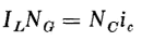
Since the impedance of gate winding II is practically zero during this interval, this current i'G circulates between the two gate windings. Next, consider the interval between π and π + α when both cores are unsaturated. The mmf exerted by the control current again demands an equal and opposing mmf in both gate windings and this constant component i'G = NCic/NG continues to circulate between gate windings during this interval. Now, at ωt = π + α, and the constant component i'G = NCic/NG again results, circulating in the same direction as before. As a result, during normal steady-state operation, there is a constant component of current circulating in one direction between the gate windings at all times in a direction such as to oppose the mmf of the control windings on both cores. The positive direction of this circulating d-c component is into the polarity-marked side of gate winding II and out of the polarity-marked side of gate winding I. During the interval of saturation for core I, the load current IL flows through gate winding I in a direction opposite to the constant circulating component. One-half cycle later core II saturates and the load current flows through gate winding II against the constant unidirectional circulating current. The wave forms of the load component and the constant component of i'GI are shown in Fig. 7-9(e), that of the total current iGI in gate winding I, which is the sum of these components, is shown in Fig. 7-9(f), and that of the total current iGII in gate II is shown in Fig. 7-9(g). Law of equal ampere turns The average value of the current in either gate, when taken over an entire cycle, must be zero. This means that, in the case of gate winding I, the average values of the positive component iL in Fig. 7-9(e) must equal the constant negative component NCic/NG. If IL is the average value of iL then we have
|
|||||||||||||||||
| Home Saturable Reactors Gate Windings in Parallel |
|
||||||||||||||||


Last Update: 2011-01-16