| Capacitors, Magnetic Circuits, and Transformers is a free introductory textbook on the physics of capacitors, coils, and transformers. See the editorial for more information.... |

|
Home  Saturable Reactors Load Impedance Zero Saturable Reactors Load Impedance Zero |
|||||||||||||


|
  |
||||||||||||
Load Impedance Zero
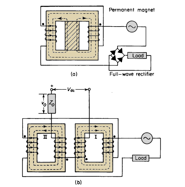
Consider the saturable reactor in Fig. 7-11(b) with the impedance of its load at zero. For the assumed idealized magnetization curve, at the instant that the a-c flux goes through zero, both cores are saturated if there is any current in the control windings. However, for the current directions shown in Fig. 7-11(b), the total flux Φ1 in core I cannot increase because it is already at the saturated value. The instantaneous a-c flux ΦacII for these current directions,
however, subtracts from the d-c flux in core II, causing this core to desaturate immediately, and its mmf must drop to zero and remain at that value until the a-c flux in core II attempts to reverse direction one half-cycle later. At that instant, the roles of cores I and II become interchanged; core I becoming unsaturated and core II remaining saturated during the second half-cycle as shown in Fig. 7-12. If the even-harmonics are suppressed completely in the control circuit, only one core at a time can be unsaturated, as each core remains saturated throughout alternate half-cycles. This is evident from the directions of currents and fluxes shown in Figs. 7-11(a) and 7-11(b). When the resistance of the gate windings is neglected and the load is short-circuited, the wave forms of the fluxes are as shown in Figs. 7-12(b) and 7-12(c). During the first half-cycle of the condition shown in Fig. 7-12, core I is saturated and core II is unsaturated. The resultant mmf acting on core II must therefore be zero, and one half-cycle later core II is saturated with core I unsaturated, producing the wave form shown in Fig. 7-12(d), for the gate current.
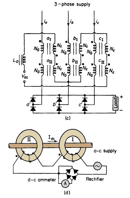
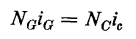
Law of equal ampere turns The law of equal ampere turns is valid for operation in which the free even-harmonics are suppressed in the control circuit. This follows from the fact that the mmf in an unsaturated core, with the idealized magnetization characteristic, must be zero, i.e.
and the gate current is expressed by
Since the control current ic is a constant unidirectional current for a given premagnetization, the gate current must have a rectangular wave form for zero load impedance. From Eq. 7-37 it may be concluded that, under practical conditions, minor variations in the magnitude and frequency will have little effect on the gate current for a given value of control current. The saturable reactor, when operating without the free even-harmonics in the control circuit, therefore provides a basically constant-current source. Flux and voltage relations The flux swing is related to the applied voltage in accordance with
The voltage induced in the control winding appears across the series impedance Z0 in the control circuit, and for the assumed ideal conditions has an rms value of
|
|||||||||||||
| Home Saturable Reactors Load Impedance Zero |
|
||||||||||||


Last Update: 2011-02-16