| Lectures on Physics has been derived from Benjamin Crowell's Light and Matter series of free introductory textbooks on physics. See the editorial for more information.... |
|
Home  Electricity Circuits Schematics Electricity Circuits Schematics |
||


|
  |
|
|
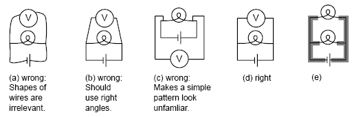
SchematicsI see a chess position; Kasparov sees an interesting Ruy Lopez variation. To the uninitiated a schematic may look as unintelligible as Mayan hieroglyphs, but even a little bit of eye training can go a long way toward making its meaning leap off the page. A schematic is a stylized and simplified drawing of a circuit. The purpose is to eliminate as many irrelevant features as possible, so that the relevant ones are easier to pick out. An example of an irrelevant feature is the physical shape, length, and diameter of a wire. In nearly all circuits, it is a good approximation to assume that the wires are perfect conductors, so that any piece of wire uninterrupted by other components has constant voltage throughout it. Changing the length of the wire, for instance, does not change this fact. (Of course if we used miles and miles of wire, as in a telephone line, the wire's resistance would start to add up, and its length would start to matter.) The shapes of the wires are likewise irrelevant, so we draw them with standardized, stylized shapes made only of vertical and horizontal lines with right-angle bends in them. This has the effect of making similar circuits look more alike and helping us to recognize familiar patterns, just as words in a newspaper are easier to recognize than handwritten ones. Figures a-d show some examples of these concepts.
The most important first step in learning to read schematics is to learn to recognize contiguous pieces of wire which must have constant voltage throughout. In figure (e), for example, the two shaded E-shaped pieces of wire must each have constant voltage. This focuses our attention on two of the main unknowns we'd like to be able to predict: the voltage of the left- hand E and the voltage of the one on the right.
|
||
| Home Electricity Circuits Schematics |
|
|